Overview
The servo tester presented here is equipped with a PIC controller to provide for very accurate pulse generation (pulse width: 1 ms – 2 ms) especially in comparison with a simpler construction with RC links. For this purpose, the internal oscillator is used, which is specified in the selected range of the supply voltage with an accuracy of 1 %.
Furthermore, the servo tester is characterized by the fact that, in contrast to other simpler digital devices, the supply voltage range is specified form 4.8 V – 6 V. With this, the servo tester can also be connected to the BEC connection of a speed controller. The polarity of the pulse for servo control can be adjusted by hardware (jumper setting).
In addition, the Servo Tester enables the use of servos for other applications, such as for rotating and panning surveillance cameras.
Circuit
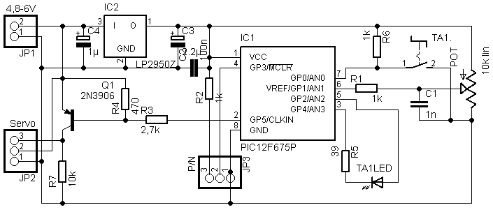
The circuit is based on the PIC12F675, which controls the servo tester. The supply voltage of the controller is lowered to 3.3 V by a corresponding controller; this ensures the highest accuracy of the internal oscillator on the one hand and the large supply voltage range of the tester on the other hand.
However, this approach requires a driver transistor Q1, which performs the level adjustment to control the servo. The supply voltage of the servo is directly looped through, so that servos or motor controllers can be tested either with the already existing battery / BEC supply by the speed controller or by means of an additional power supply (in this configuration it must be ensured that no power is provided via the servo plug).
The jumper JP3 determines the polarity of the control pulse for the servo. Please note that the LED is a bi-color LED.
Operation
The operation is simple and intuitive. The servo tester has two different operating modes: the manual mode, in which the servo is controlled by a rotary knob P1 and the neutral position can be adjusted and the exercise mode, in which the servo is continuosly moving between the end points. The change between the two operating modes is carried out by pressing the button S1. The LED will indicate the active mode of the servo tester.
After switching on, the device is in manual mode and the servo position is adjusted by rotation of the potentiometer P1. In the pulse area outside the window of 1.45 ms and 1.55 ms, the LED lights up in green. To move the servo to the neutral position, the color of the LED within the window of 1.45 – 1.55 ms changes to yellow or both colors of the LED light up and when the neutral position of 1.5 ms is reached, red is finally displayed; no button has to be pressed and both hands are free to perform adjustment work if necessary.
The Exercise Mode offers two speeds to choose from. The LED flashes red in this mode and shows which speed was selected via its flashing frequency (0.25 s corresponding to 2 x flashing/second or 15 s (correspondingly once 2 s on, then 2 s off) from final rash to final rash). The speed is switched by turning the potentiometer: if a pulse length greater than 1.5 ms is set, then the Exercise Mode is selected at high speed, otherwise the servo is controlled slowly.
Software Download
The firmware for the servo tester (Release 1.0) is freeware, which can be used without restrictions for private, non-commercial purposes according to the underlying End User License Agreement (EULA).
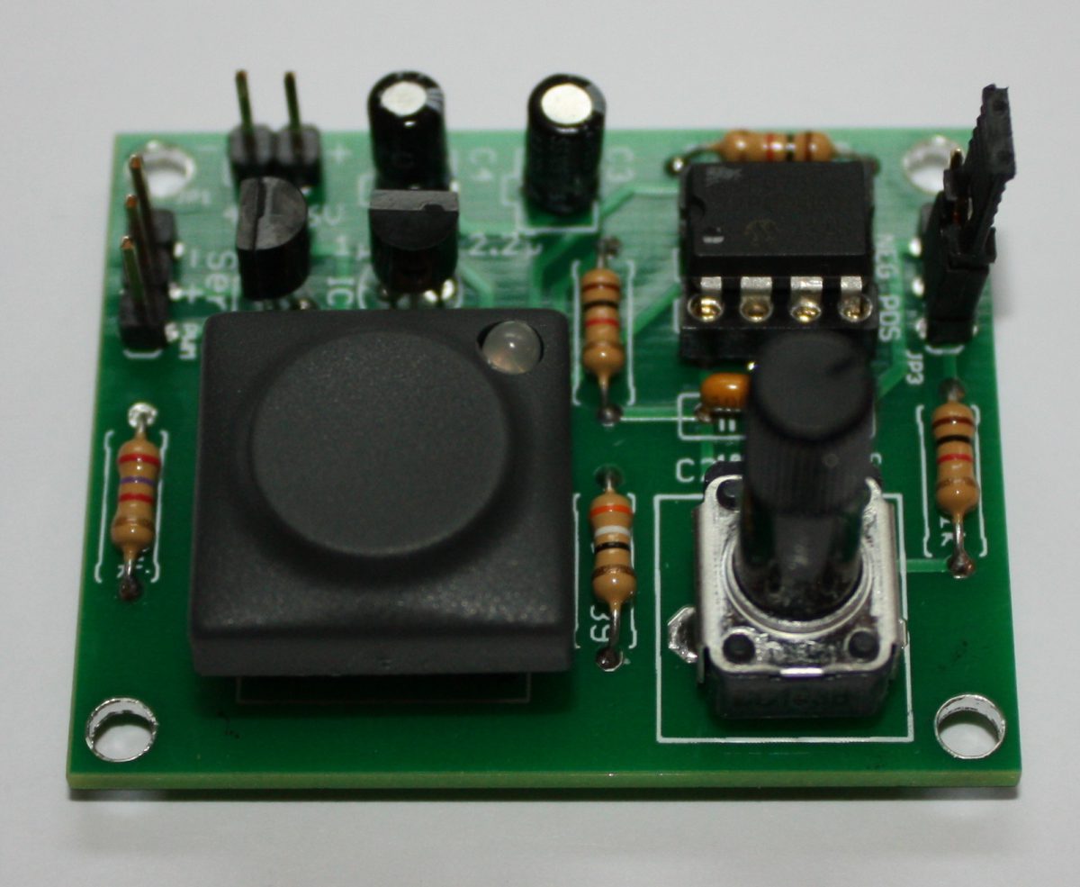
Servotester kit and components
In my shop you will find a complete kit for the tester.