Remote control with gamepad or joystick

Overview

In the previous article we already presented the possibility to control up to eight servos via a USB interface using a joystick or gamepad, a PC and a PiKoder/SSC. Here is now described how a wireless model remote control can be realized with a PiKoder – receiver, the PiKoder/SSC RX. Bluetooth for command transmission.

Setup

First, the PiKoder/SSC RX must be connected to the PC at the operating system level. For this purpose, you first search for new Bluetooth devices in the device control.

After a short time, the Bluetooth module of the receiver should be offered. The PIN is “1234”.

With the selection “Connect” the coupling (pairing) takes place on system level.

As the following view from the device manager shows, the coupling of the system also establishes two virtual serial interfaces, which we access later in the program for establishing a connection.

This completes the setup and the JoystickRC program can now be started as described in the previous post.

DiddyBorg with QGroundControl – remote control joystick

In this blog I describe how I evolved the joystick / gamepad remote control of my RPI-controlled DiddyBorg to QGroundControl and MAVLink as communication protocol.

This has given me the basis to process more sensors in a standard environment in the future and to plan and execute missions for the DiddyBorg.

Software installation on the Raspberry Pi (RPi)

On the RPi, first install pymavlink, the Python version of the MAVLink libraries. The easiest way to do this is with PIP:

pip install pymavlink

After that you have to replace the module mavutil.py, because otherwise there will be no connection between the RPi and QGroundControl due to a pymavlink-issue. To do this, find the installation location of the pymavlink library with:

pip list -v  

Then replace the mavutil.py module with the version in the github repository for this blog. The new version is backward compatible.

Finally, create a directory, e.g. diddy2QGC into which you copy the Python modules diddy2QGroundControl.py and ThunderBorg3.py. In this directory you then start the Python script later with:

 python diddy2QGroundControl.py

Software installation on the desktop

Install QGroundControl on your desktop.

Starting the applications

Make sure the RPi and your desktop are on the same network and run QGroundControl (QGC) and the Python script (the order is irrelevant).

The DiddyBorg logs into the QGC and you will then find the option to teach your joystick in the Vehicle settings. Please note that diddy2QGroundControl.py in mode 2 uses the roll channel for right/left control and the inverted value of the pitch channel for motor control.

Remote control DiddyBorg with gamepad or joystick

In this blog I present my Windows app JoystickRC4DiddyBorg for remote control of the DiddyBorg (from PiBorg) with a joystick or gamepad.

The DiddyBorg sample programs published by the manufacturer PiBorg also include a Python remote control script with joystick, but it uses Bluetooth and therefore has a rather limited range.

The app presented here uses the existing WLAN and UDP as protocol to ensure sufficient agility of the remote control. For safety reasons, the time-out logic of the ThunderBorg motor controller is activated.

Software installation

The DiddyBorg needs a Python script JoystickRC4DiddyBorg as receiver, which you can find on github.com. In addition to the receiver program, you will also find a version of the ThunderBorg – Library for Python 3.x in the repository (the sample programs for the DiddyBorg are still based on Python 2.x).

The easiest way is to copy the two files additionally into the directory with the examples – then the script should work without further adjustments of path names.

On the PC side, install the Windows app JoystickRC4DiddyBorg of the same name, which you can get for free from the Microsoft App Store.

Operation

First start the Python script on the DiddyBorg. If you have a screen connected, then the program will log in and indicate that it is waiting for a client.

When you start the PC app, it will automatically search for a DiddyBorg with an active and compatible receiver on the local WLAN (to which both the DiddyBorg and the PC being used must be connected). If no connection can be established, a corresponding error message is displayed.

After the connection has been successfully established, the channels can be assigned to the various joystick axes and keys. Channels 3 and 4 are used as push buttons and allow for example fast / slow rotation (the function of the push buttons can be traced in the Python script).

The assignment of the channels is saved and restored at the next program start.

Joystick model remote control with multi-protocol TX module iRangeX IRX4 +

In the two previous articles on model remote control with joystick, a “completely normal” remote control transmitter was used to transmit commands. The control sticks and various switches of the transmitter were not needed because the control itself is done by the joystick.

The overall structure can therefore be simplified by using a multi-protocol TX module such as the iRangeX iRX4 + instead of the complete remote control transmitter.

The module can – just like the remote control transmitter – be controlled directly via the PPM signal from the USB2PPM – PiKoder. Since the iRangeX already operates with an operating voltage of 5 volts, the power supply is also provided via the USB2PPM PiKoder and no additional battery is required.

Setup

The USB2PPM PiKoder is set up according to the instructions. Even if you have only equipped one cynch socket so far, the three-pin header can be retrofitted without any problems.

The connection between the iRX4 + module is made via a three-wire cable (Vcc, PPM and Gnd) (see picture below left). At one end of the cable there is a three-pin socket for plugging into the corresponding pin header of the USB2PPM, on the other side the five sockets of the module are adapted – you can see the pin assignment that the module expects in the picture on the right.

No further adjustments or changes are required.

And the structure described here can of course also be used in connection with a Windows notebook.

Joystick model remote control with Spektrum DXe (2)

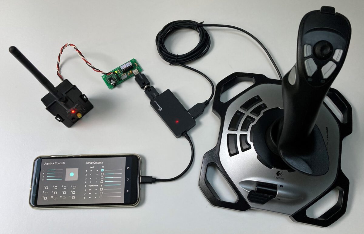
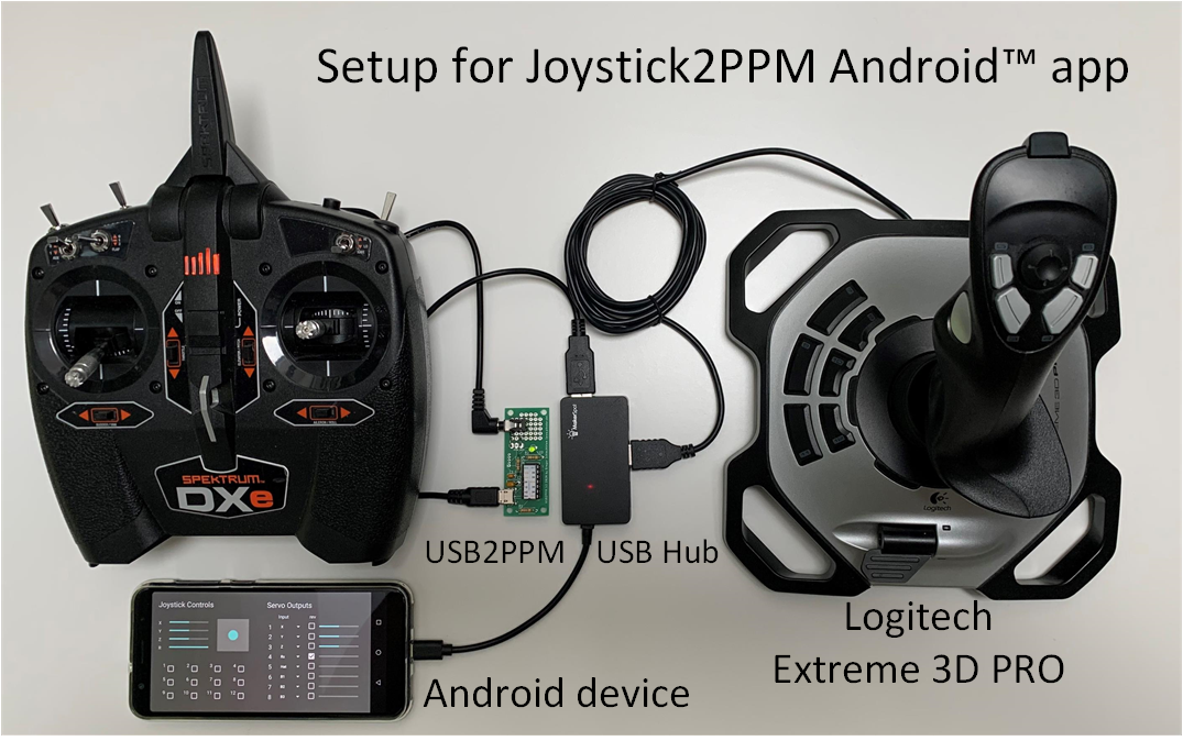
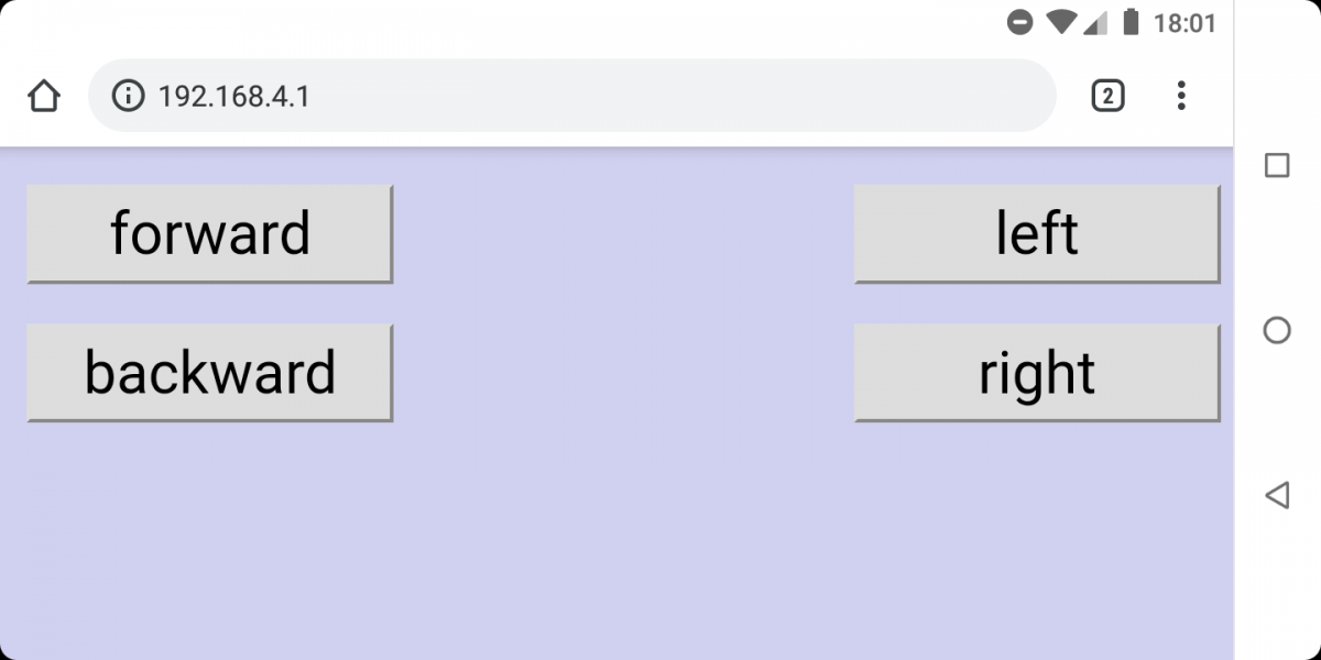
The first entry in this series used a notebook to translate the joystick inputs into commands for the USB2PPM. Alternatively, an Android (TM) smart device with a corresponding app can be used for selected joysticks.

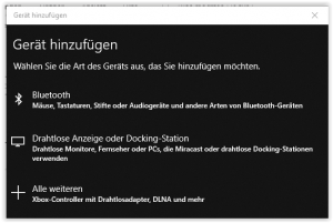
The hardware structure in the title picture is the same as the configuration in the Part 1 Except for the computer, which is replaced by the smart device, and the hub: a USB OTG hub must be used in conjunction with the smart device.

With regard to the preparation of the remote control transmitter, the same considerations for ergonomics apply and it is advisable to expand the remote control with a switch as described in Part 1.

With regard to the app itself, you can choose between the free app Joystick2PPM and a special app for quadrocopters Joystick4UAV (see below); you can find both apps in the Google Play Store.

Joystick2PPM (Android App)

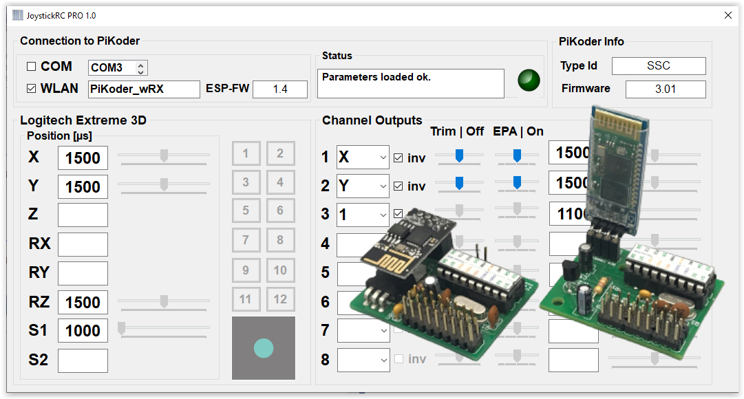
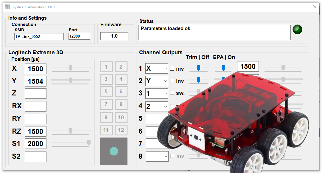
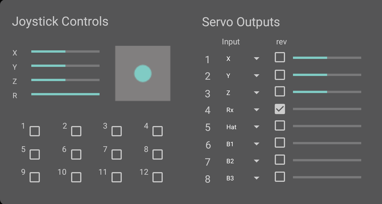
The user interface of the app largely corresponds to the Windows implementation and is intuitive and easy to understand. The joystick controls are on the left and the servo channels are mapped to the right with drop-down boxes.

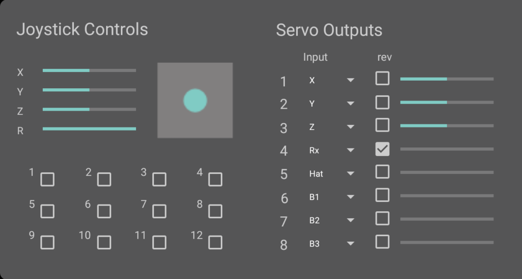
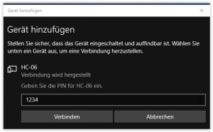
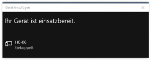
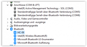
The joystick and the USB2PPM are automatically recognized after starting the APP. When using the application for the first time, the user must enable access to the corresponding USB interfaces.

Please note that the app currently only supports a limited number of joysticks and other operating devices. The current list of the compatible devices can be found in the Playstore at any time.

Joystick4UAV (Android App)

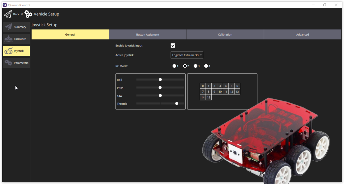
The Joystick4UAV app is an advanced version of the Joystick2PPM application, which is geared towards the needs of remote control of quadrocopters or other vehicles (UGV) and boats (USV) with a flight controller.

The basic structure of the Joystick4UAV corresponds to the apps already described. The four joystick axes are mapped to the remote control channels 1-4 according to the usual assignment for flight controllers. You can of course adapt this assignment within the four channels according to your preferences. All channels can be inverted by checking the associated box.

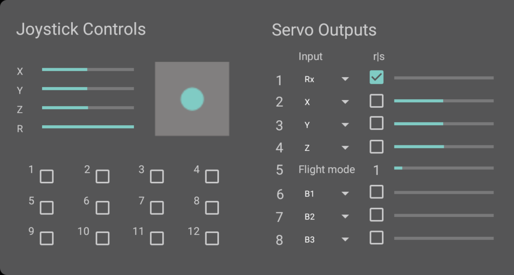
The flight mode is coded in channel 5. There are six modes available. The flight mode selection takes place by pushing the joystick buttons 7-12 (see figure below right), where button 7 sets flight mode “1” and button 12 sets flight mode “6”. The selected flight mode is displayed numerically (“1” in the picture above) and the bar corresponds to the transmitted channel value.

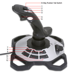
The remaining buttons 1-6 (button B1 .. B6 in the upper area) and the hat switch are available for special functions and can be assigned to channels 6-8 as required. If the box belonging to the channel is activated, the button behaves as a switch.

Please note that only the Logitech Extreme 3D Pro joystick is currently supported in the app.

RC with your web browser – more intuitive and more agile

In previous blogs related to RC with a web browser I presented solutions which were suited for simple and none time critical applications due to the user interface and the system response time.

The initial concept of a button based user control was relatively slow because the web page had to be re-transmitted and rebuild on the client side after each user interaction.

The improved “joystick”-based interface was already deploying AJAX to improve the system agility. However, in order to initiate a command you would have to touch the screen and to stop the movement you would have to touch the screen at another location which is not very intuitive. You would probably expect a movement to last as long as you touch the screen.

The latest version of httpRC presented here does address both requirements based on a button based UI: a command is executed only as long as you touch it in a very agile way.

The source code for the ESP8266-01 is provided through github and the programming itself can be done via the programming adapter described earlier.

Additional information regarding the receiver kit you would find on the respective PiKoder page.

Arduino based XBee radio control

Combine the Arduino based open source digital radio control arduinodtx with an intelligent serial servo controller such as the PiKoder/SSC, an Arduino XBee shield and an XBee module to easily build a feature rich radio control.

A transparent transmission is used, so that no adjustments to the Arduino software or the PiKoder/SSC firmware are required; the full range of functions of the remote control is available.

The setup of the transmitter including the jumper configuration is shown below – for details regarding the wiring please refer to the arduinodtx webpage.

xbee-digital-rc_404p

The configuration of the receiver comprised of an XBee breakout adapter, the PiKoder/SSC board and a dc-dc converter to generate the 3,3 Volt required by the receiver is shown below. For more details – including the programming of the XBee modules – please refer to the PiKoder/SSC Application Note #3: XBee Communication.

complete-receiver-unit

Prototyp receiver setup