Remote control with gamepad or joystick

Overview

In the previous article we already presented the possibility to control up to eight servos via a USB interface using a joystick or gamepad, a PC and a PiKoder/SSC. Here is now described how a wireless model remote control can be realized with a PiKoder – receiver, the PiKoder/SSC RX. Bluetooth for command transmission.

Setup

First, the PiKoder/SSC RX must be connected to the PC at the operating system level. For this purpose, you first search for new Bluetooth devices in the device control.

After a short time, the Bluetooth module of the receiver should be offered. The PIN is “1234”.

With the selection “Connect” the coupling (pairing) takes place on system level.

As the following view from the device manager shows, the coupling of the system also establishes two virtual serial interfaces, which we access later in the program for establishing a connection.

This completes the setup and the JoystickRC program can now be started as described in the previous post.

RC with your web browser – more intuitive and more agile

In previous blogs related to RC with a web browser I presented solutions which were suited for simple and none time critical applications due to the user interface and the system response time.

The initial concept of a button based user control was relatively slow because the web page had to be re-transmitted and rebuild on the client side after each user interaction.

The improved “joystick”-based interface was already deploying AJAX to improve the system agility. However, in order to initiate a command you would have to touch the screen and to stop the movement you would have to touch the screen at another location which is not very intuitive. You would probably expect a movement to last as long as you touch the screen.

The latest version of httpRC presented here does address both requirements based on a button based UI: a command is executed only as long as you touch it in a very agile way.

The source code for the ESP8266-01 is provided through github and the programming itself can be done via the programming adapter described earlier.

Additional information regarding the receiver kit you would find on the respective PiKoder page.

Control your Ardupilot Mega Rover with your Android Smartphone (III)

Overview

The Ardupilot Mega (APM) and other flight controllers are frequently controlled by a PPM stream rather than the parallel input per channel which I described in part 1 of this blog. The new PiKoder/PPM wRX receiver with its PPM frame output brings this capability to you. The connection between the receiver and the flight controller is reduced to a single 3 strand cable as shown in the featured image.

Description

The PiKoder/PPM wRX receiver will be controlled by the udpRC4UGV App as described in part 2 of this blog.

The feature set of the app has been extended to allow you to freely determine the position of the direction and throttle channel within the PPM frame through the app preferences.

To change the channel setting please select the respective preference and enter the channel number (1 .. 8). E.g. the APM Rover configuration features direction on channel 1 and throttle on channel 3.

Please note that setting the APM’s input mode from parallel to PPM requires a jumper between channel 2 and channel 3 input as shown below.

Control your Ardupilot Mega Rover with your Android Smartphone (II)

Overview

As already indicated in the previous blog on the topic “Ardupilot Mega Rover with the smartphone remote control“, now, after some further work on the topic, a new Android(TM) app “udpRC4UGV” with rover-specific functions is available. The most important enhancements are the selection of the flight mode and the toggling of channel 7 making a number of APM special functions available.

Description

As outlined in the previous blog a PiKoder/SSC wRX receiver replaces the standard RC receiver in the rover. The smartphone RC uses WLAN for command transmission: the PiKoder does offer an access point (AP) to which the smartphone will connect.

The remote control app offers a variety of user interfaces: from simple key control to a virtual joystick to an accelerometer-based option.

In addition to the general controls for remote control, each user interface also offers the possibility to choose the flight mode. In addition, channel 7 can be triggered via the “CH7” button (for example, in LEARNING mode, the current position is saved as a waypoint).

The app is available free of charge from the Google Play Store. The User Manual can be downloaded from the PiKoder website; it describes not only the program operation in detail, but also the hardware setup.

RC model control with web browser – improved user interface

A few days ago I came across the ESP8266 MikroE Buggy project.

In this project, a web server is implemented on the ESP8266 – similar to my blog Model Remote Control with Web browser. Using this concept, a browser based (and therefore operating system neutral) radio control could be easily made available. In this project, especially the HTML5 based user interface implementing a joystick caught my attention.

The software is open source and so I was able to change the program for use with a PiKoder/SSC wRX. Additionally, I adapted the code for controlling a ‘normal’ car or boat (one channel for speed, one channel for direction). The customized source code is available in a github repository.

The programming of the ESP8266 is also described in the web browser model remote control blog. An additional feature of the ESP8266 MikroE Buggy project is that the Arduino file system is used. The installation and use is described here.

Open Source Arduino Digital RC Transmitter

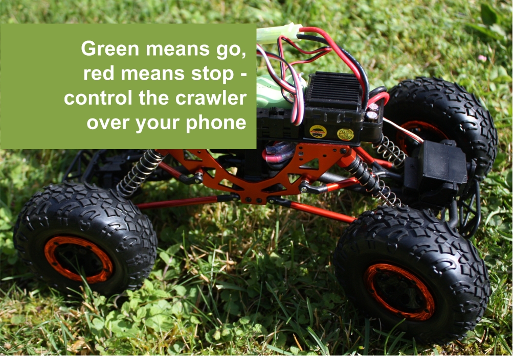
The sketch ArduinoDTX implements a feature rich RC addressing all needs of a state-of-the-art transmitter on an Arduino. It is based on fully digital encoding of all control information in the miniSSC – protocol rather than using a PPM frame. This fully digital encoding enables transmitting over a transparent serial channel such as Bluetooth, Wifi, and XBee. As a receiver for e.g. Bluetooth a PiKoder/SSC RX would be deployed.

This digital RC transmitter is based on the Open Source project arduinorc by Richard Goutorbe and thus inheriting the respective full feature set such as:

  • up to 9 proportional channels (Nano), 6 channels by default (Uno)
  • up to 6 additional digital channels (switches)
  • 9 model memories
  • Dual rate/Exponential switch
  • Throttle cut switch
  • 2 programmable mixers
  • End point adjustment, Potentiometer and Servo calibration
  • Throttle security check at startup
  • Optional Transmitter battery low voltage alarm
  • Programmable with Linux or Windows via USB (terminal application)

The original arduinorc-sketch has been modified and became the ArduinoDTx sketch, which outputs all channel information in the miniSSC-format rather than a PPM-pulse frame on Arduino pin D6. Every time a stick position would change a miniSSC message is generated. The PPM output has been removed completely.

The ArduinoDTx sketch is open source and provided through a respective github repository under the terms of the GNU General Public License Version 3.

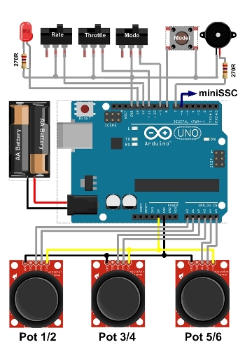
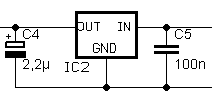
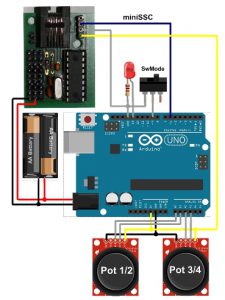
Prototype setup: Digital four channel RC

Schematic setup of the Arduino Digtial RC transmitter

An RC transmitter with four channels will serve as a prototype project. As shown in the image two Thumb-Joysticks are evaluated by the Arduino (Pot 1/2 and Pot 3/4 in the above schematic). The connection to the Arduino’s analog pins is through a proto-shield. This shield does also accomodate the mode switch and the LED with the respective 270R resistor.

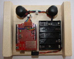
The RC is designed for battery operation. To guarantee the required minimum voltage of 6 V for the Arduino – even when using rechargeable batteries with a nominal voltage of 1,2 V – a battery holder for five AA elements has been selected. The two side panels support your palm operating the remote control and would enhance the user comfort significantly.

Please note that the USB port of the Arduino is easily accessible. This allows you to download software upgrades but also to customize the RC to your application.

Commissioning and testing

Test setup Arduino Digtial RC transmitter

For commissioning the RC you would download the arduinodtx sketch (.ino-file) which is provided through an respective github repository. Please note that building the sketch requires the Arduino “TimerOne”-library.

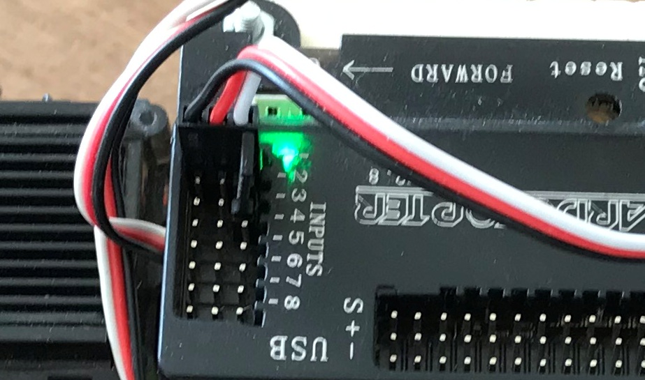
After you have uploaded the sketch to your Arduino the easiest way to test the RC would be to build the “wired remote control” shown to the right using a PiKoder/SSC evalutation board. In the standard configuration the pots 1-4 would control the respective servo channels 1-4 of the PiKoder/SSC.

If you wanted to customize your RC transmitter then you would hve to follow the steps described on the arduinorc-page. All commandos for programming the arduinorc are still available to you – for more information please refer to the (arduinorc command documentation).

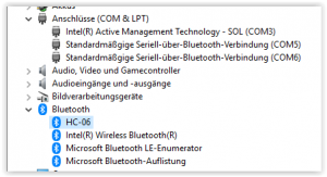
Using Bluetooth communication

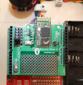
Bluetooth shield configuration for Arduino Digtial RC transmitter

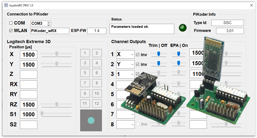
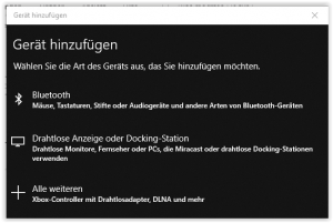
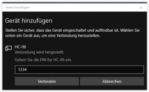
You can easily customize the digital remote control to a Bluetooth RC with an ITEAD-Bluetooth Shield and then use the PiKoder/SSC RX as a readily available and fully compatible 8 channel receiver. Since the transmission is based on a tranparent serial protocol there are no changes needed in the sketch and the complete feature set is also available for the Bluetooth RC.

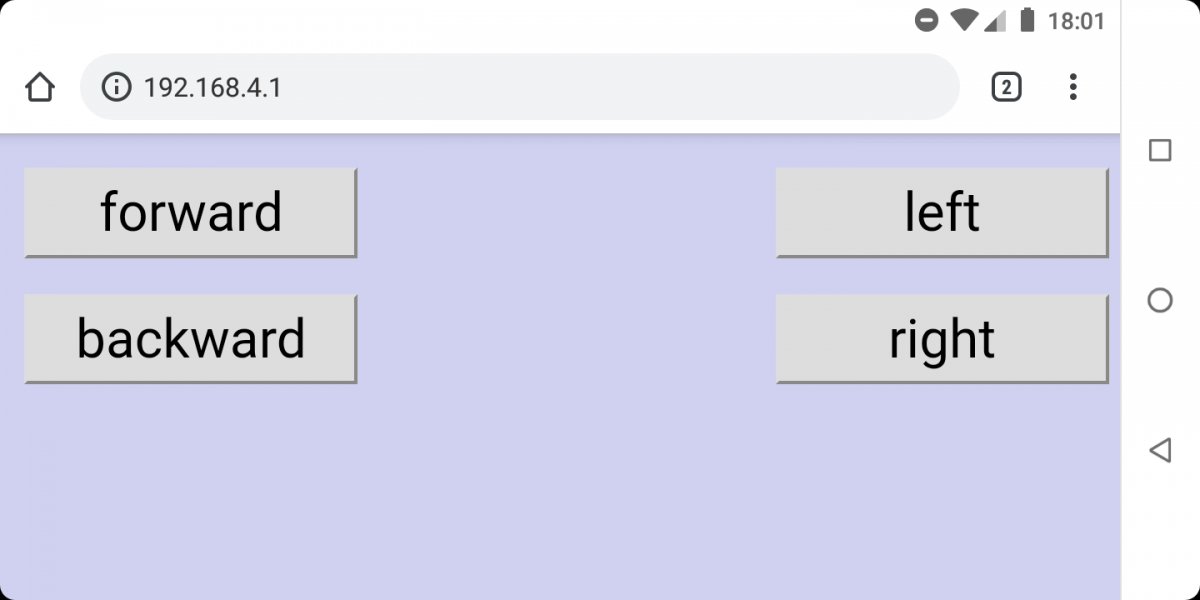
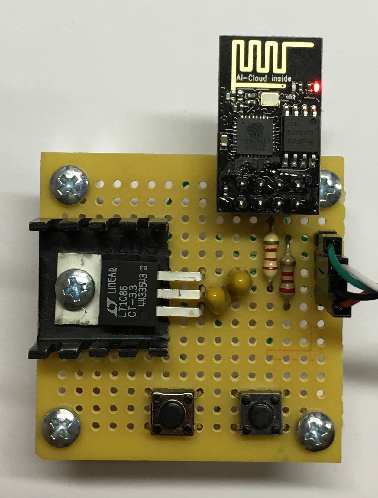
The transmitter setup is shown in the image. Prior to operating the RC the connection between the wifi modules has to be configured. Please refer to the PiKoder/SSC RX User Manual for a detailed description.

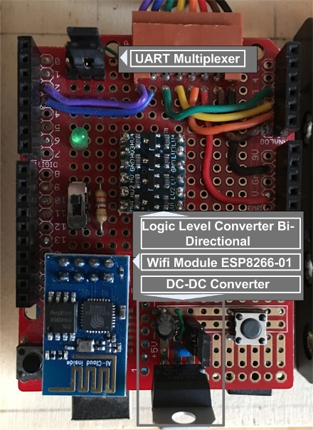
Using WLAN communication

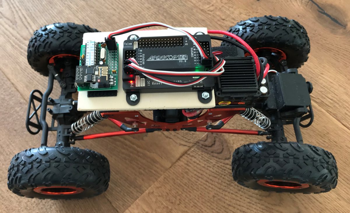
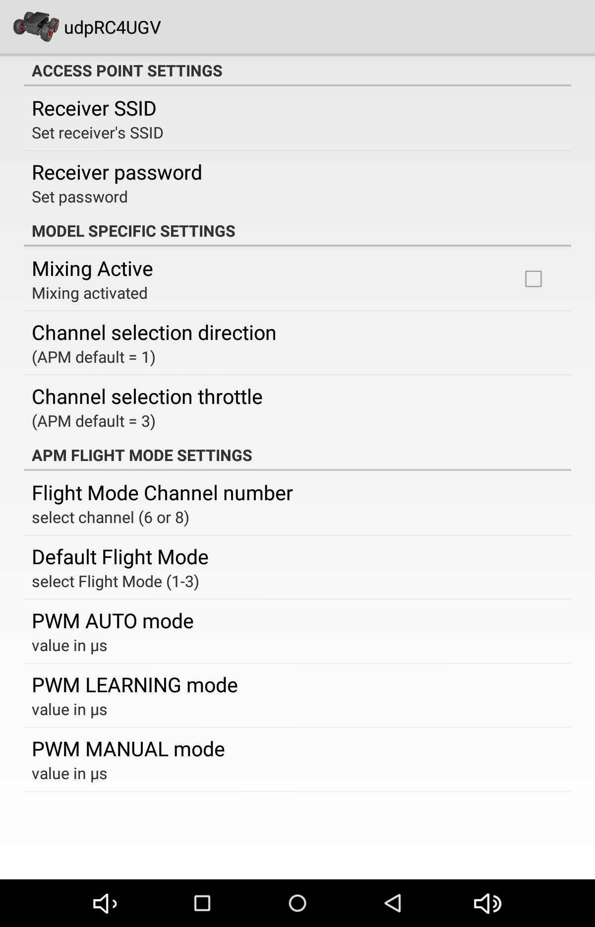
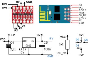
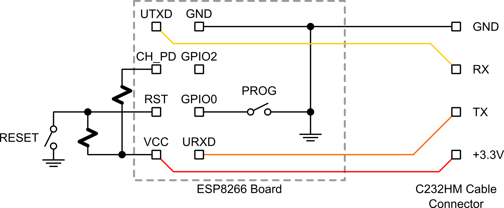
You can also easily customize the digital remote control to a Wifi RC by adding a logic level converter, a dc-dc converter, two jumpers as UART multiplexers (to allow for programming the wifi radio) and an ESP8266-01 Wifi module and then use the PiKoder/SSC wRX as a readily available and fully compatible 8 channel receiver. The hardware setup and the programming of the wifi radios is described in great detail in the blog Arduino WLAN RC Transmitter.

Additional Application Examples

In order to increase the range of your radio control you can upgrade from Bluetooth to XBee. The setup is described in the blog Arduino based XBee radio control and in the PiKoder/SSC Application Note #3: XBee Communication.

ESP8266-01 Sketch for the PiKoder/SSC wRX receiver

The PiKoder/SSC wRX uses the ESP8266-01 module configured as an Access Point (AP) to implement a transparent serial communication channel between a transmitter a PiKoder/SSC. The ESP8266-01 can be programmed as needed based on its default firmware by using respective AT commands. However, given the number of parameters used for the commands this approach is complex and rather error prone. In addition, the verification of the programming is difficult and mistakes very often require to re-flash the ESP8266.

It has turned out to be significantly easier to flash the ESP8266-01 with a dedicated sketch, which implements all the features required for the serial communication and offers an additional command interface for setting the AP parameters needed.

This sketch udpRC_ESP8266-01 is Open Source and is provided via github for download. The sketch will be compiled and uploaded to the ESP8266-01 via the Arduino IDE as described in the blog RC with your webbrowser.

The use of the re-programmed module is very simple and intuitive. After rebooting the sketch would check the non-volatile memory of the ESP8266 for a valid parameter set. If no parameters are found then the default values will be used. After rebooting the the Controller is ready to operate.

The screenshot shows the user interface and the available commends. After rebooting the ESP8266-01 sents a more or less unreadable stream of characters to indicate that it is ready.

Entering the command ‘$?<cr><lf>’ will echo the current parameter setting. The SSID of the AP would be changed with the command ‘$s=’ followed by <cr><lf> and for changing the password you would use ‘$p=’. The revised parameter will be stored right away but will only be applied after a reboot. You can always check the changed parameter settings with ‘$?<cr><lf>’.

Radio control with your webbrowser

If your rc model would offer an access point and run a webserver, then you could control your model with a webbrowser running on your smartphone – no matter whether this is a Windows or Android device or an iPhone.

The PiKoder/SSC wRX (see below) is well suited as a hardware platform for this concept: the ESP8266-01 offers the access point and runs the webserver, the PiKoder/SSC manages all realtime aspects of controlling the servos and the electronic speed control.

pikoder_ssc_wrx-catalogue-image-png

PiKoder/SSC wRX

The standard configuration of the PiKoder/SSC wRX requires the ESP8266-01 to act as a transparent bridge. Since we will be needing a webserver, we would have to flash this wifi controller with a new firmware. This can be easily accomplished by using the latest Arduino IDE which is supporting generic ESP8266 modules.

The new controller firmware is open source and would be available through the github repository makerprojects/httpRC. After downloading open the sketch in the Arduino IDE. At the beginning of the source code you will find the settings recommended for compiling the program. [Update December 27, 2018: The httpRC sketch has been completely revised and updated. Please check this blog for more details.]

In order to flash the ESP8266-01 you will need an USB-Serial converter, since the wifi module does not feature a USB port. Please keep in mind also, that the ESP8266 requires a supply voltage of 3,3 Volts – the board is not 5 V tolerant! The offering of USB-Serial converter offering a 3,3 Volt supply as well as 3,3 Volt signal level is limited; therefore it might be easier to use a converter with 5 V supply and 3,3 V signal level such as the PL2303TA readily available at ebay (shown below) and build your own converter from 5 V to 3,3 V.

usb-connector-ebay

USB-Serial connector

Since you would need a “reset” and “program” button for flashing the module you might consider to construct the little adapter shown below using a prototype board.

programmieradapter-esp8266

Programming adapter for the ESP8266-01

The schematic for the programming is shown below.

esp8266_flash_prog_board_sch

The conversion of the 5 V provided by the USB-Serial adapter to 3,3 V follows the design of the PiKoder/SSC wRX and requires a standard low drop voltage controller LF 33 CV ( please refer to the following excerpt of the PiKoder/SSC wRX schematic; the 5 V input would be to the left, the output is to the right).

spannungsanpassung

Unfortunately the flashing of the ESP8266 does not start automatically as you might be used to when downloading a program into your Arduino but has to be initiated manually. You would push the RST and PROG button simultaneously and release the RST button while still holding the PROG button. After releasing the PROG button, the module would be in flash mode. Now you would start uploading the program. Now you would start uploading the program. Once the upload is complete your controller would require another reset prior to being operational. Once the upload is complete your controller would require another reset prior to being operational.