Metz Mecatron transmitter 191/1 – conversion into Baby 2 transmitter 191/11?

Some time ago I bought a Metz remote control transmitter 191/1 on ebay. The description stated that the transmitter had been converted to a connection to 12 volts (plug for cigarette lighter).

When I looked at the transmitter a few days ago, I came across an interesting inner workings: in addition to the expected DC voltage regulator for 6 volts according to the battery voltage, a circuit board was built into the battery compartment with a relay, wire potentiometer, motor and a break contact.

After a few tests and considerations, it soon became clear that the transmitter would be clocked by the motor with an interrupter. The switching disk on the motor ensures a pulse-to-pause ratio of 1: 1 and the pulse length can be adjusted via the rotary resistance.

At first this was astonishing to me, since the remote control technology of the time worked more with tone frequencies than with pulse lengths and I tried to imagine the required receiver logic.

After doing some research, I came across the following publication in Funkschau issue 21/1965, in which the process is well explained. Apparently someone has recreated the logic of the transmitter using electromechanical means.

I am not sure whether the approach worked, as my system is quite “built-in” – the integrated voltage regulator is probably the result of a later adjustment / repair, the mechanical and soldering quality are very different, so that the attempts by several owners are assumed and the structure found will certainly not work with its current wiring. But maybe this conversion was also presented in a model making or electronics magazine? – I would be very grateful for any relevant information!

The description of the Metz system in the radio show gives a pulse duration of 5 ms. This would correspond to an engine speed of 6,000 rpm. My measurements with the oscilloscope show that the contacts are at a pulse length< = Bounce heavily for 20 ms. On the other hand, based on the receiver circuit, I can also imagine that a reliable channel differentiation is possible even with larger pulse lengths. As soon as I can get hold of a working receiver, I will check my thesis.

To be continued…

Arduino remote control transmitter with iRangeX multi-protocol module

The previous blog describes the Arduino PPM encoder. Together with a multi-protocol module, you can set up a complete remote control transmitter with little additional effort.

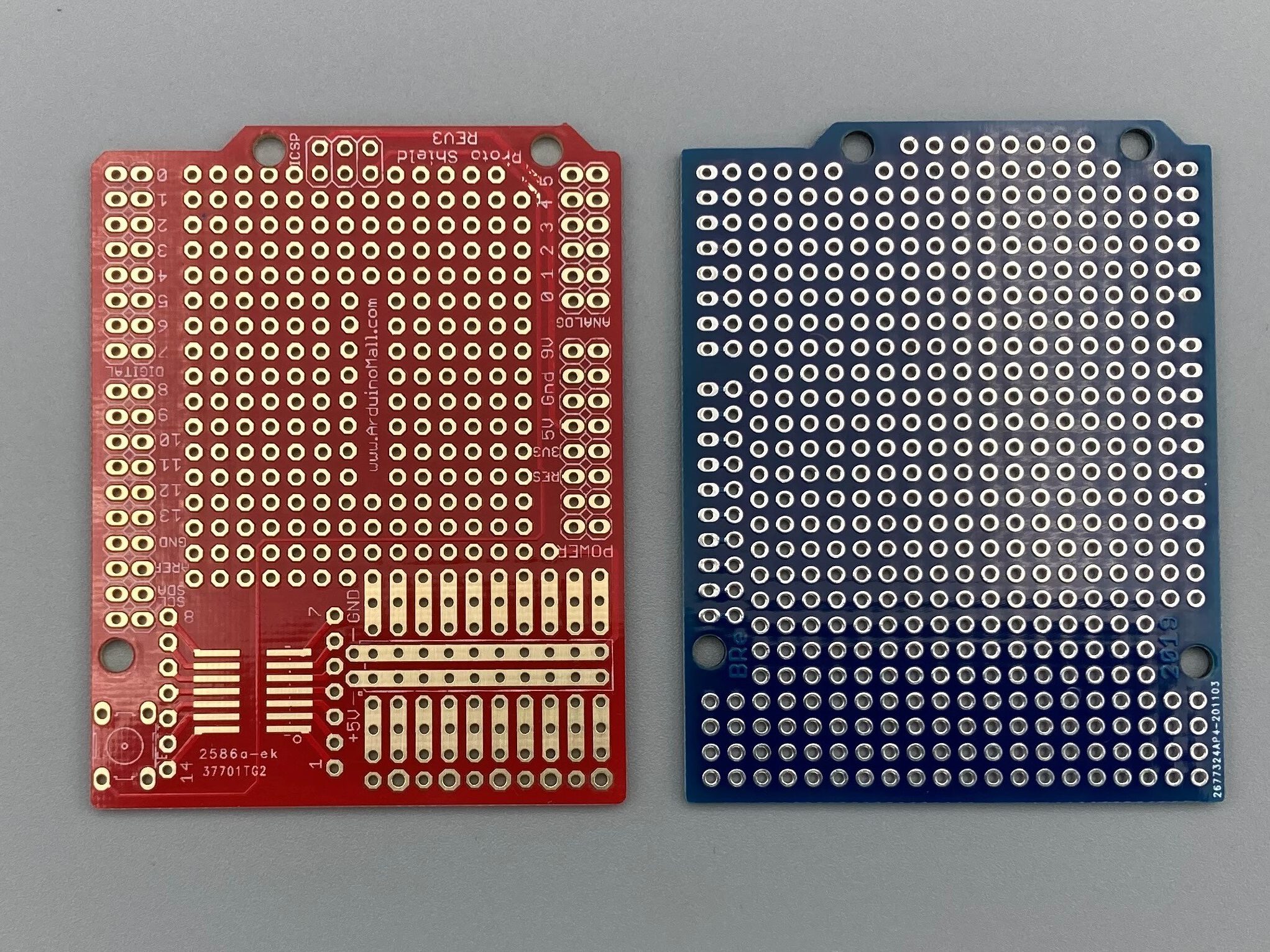
To do this, adapt the module using an Arduino prototype shield. However, not all shields are equally suitable. Some shields do not have a hole pattern in the lower right area but a specific layout like the red circuit board in the picture. But you need a prototype board with a complete breadboard like the blue circuit board.

Arduino Prototype Sields

You make the electrical connection between the Arduino and the module 
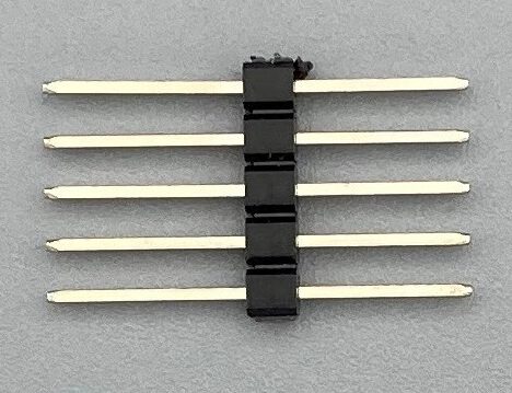
with a five-pole pin header with extra-long pins. Insert the pin header into the socket header on the back of the module. Then position the module on the prototype shield and find the correct position for the module and the soldering points that you need to use.

To ensure a secure hold, I have also provided Velcro tape. Since this additional intermediate layer changes the height of the soldering pins again, you can only solder the pins now.

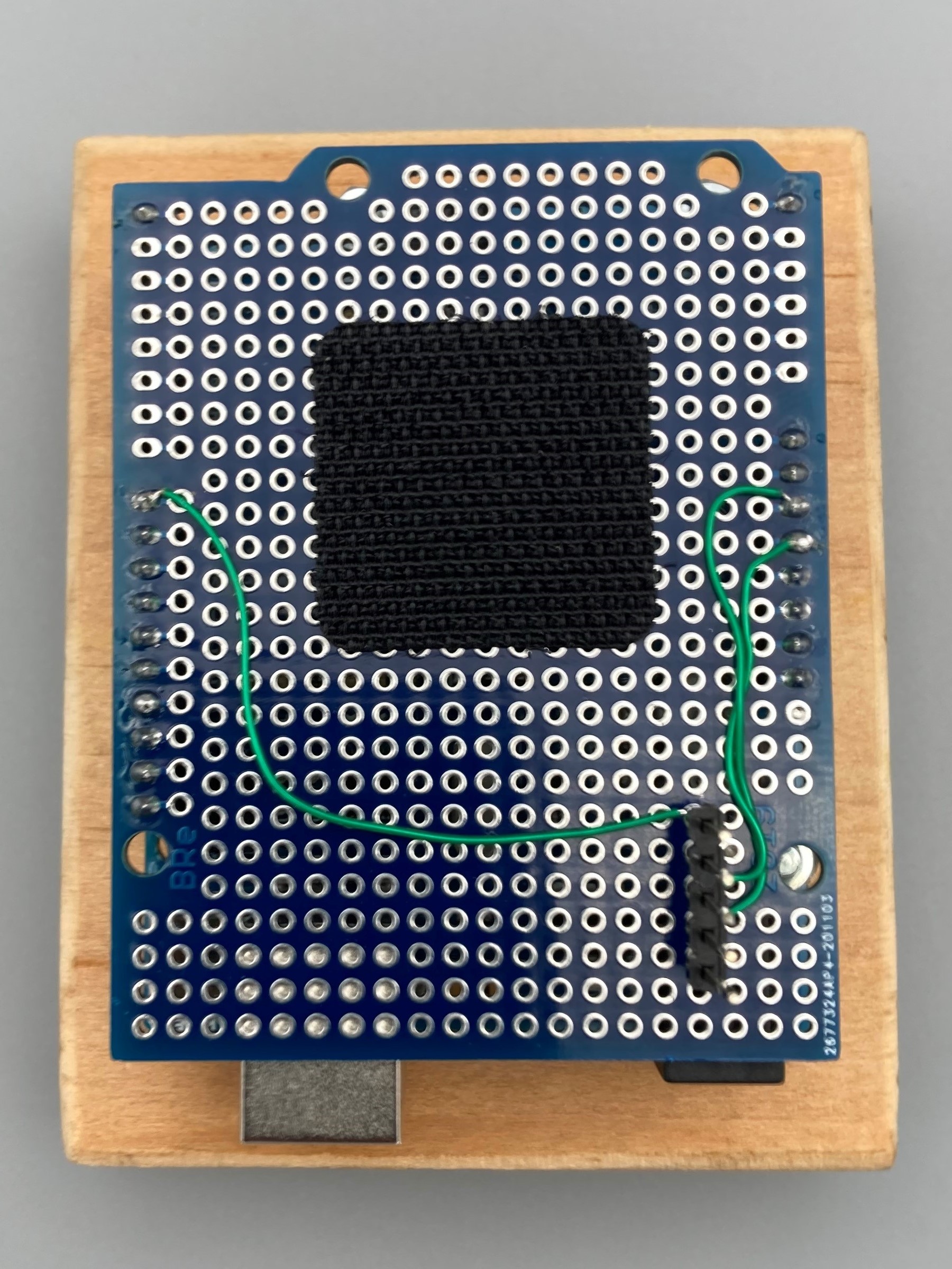
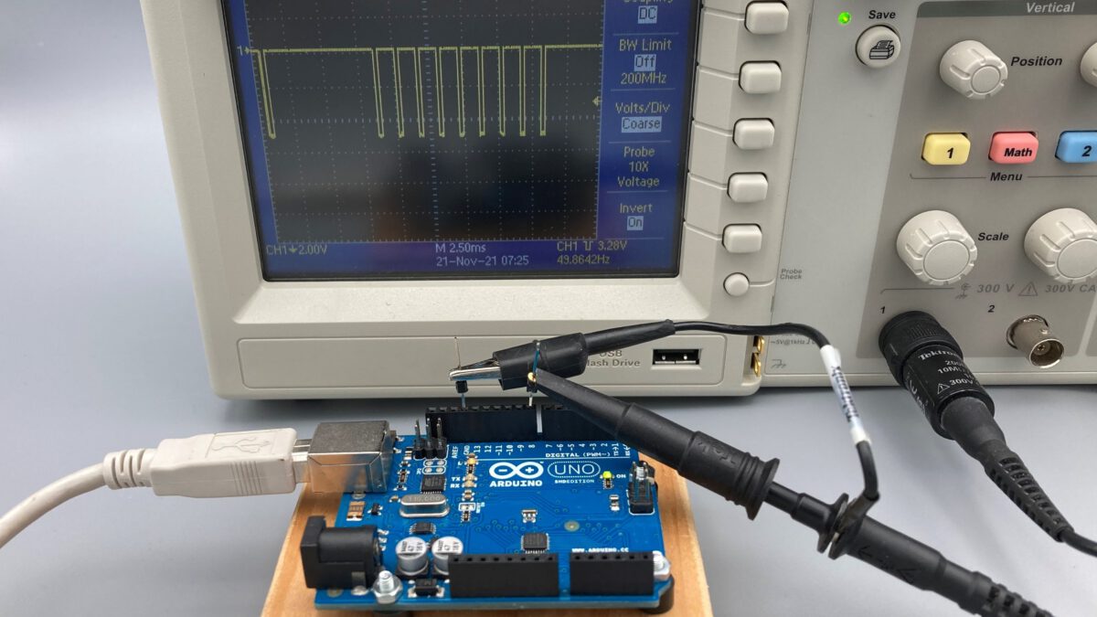
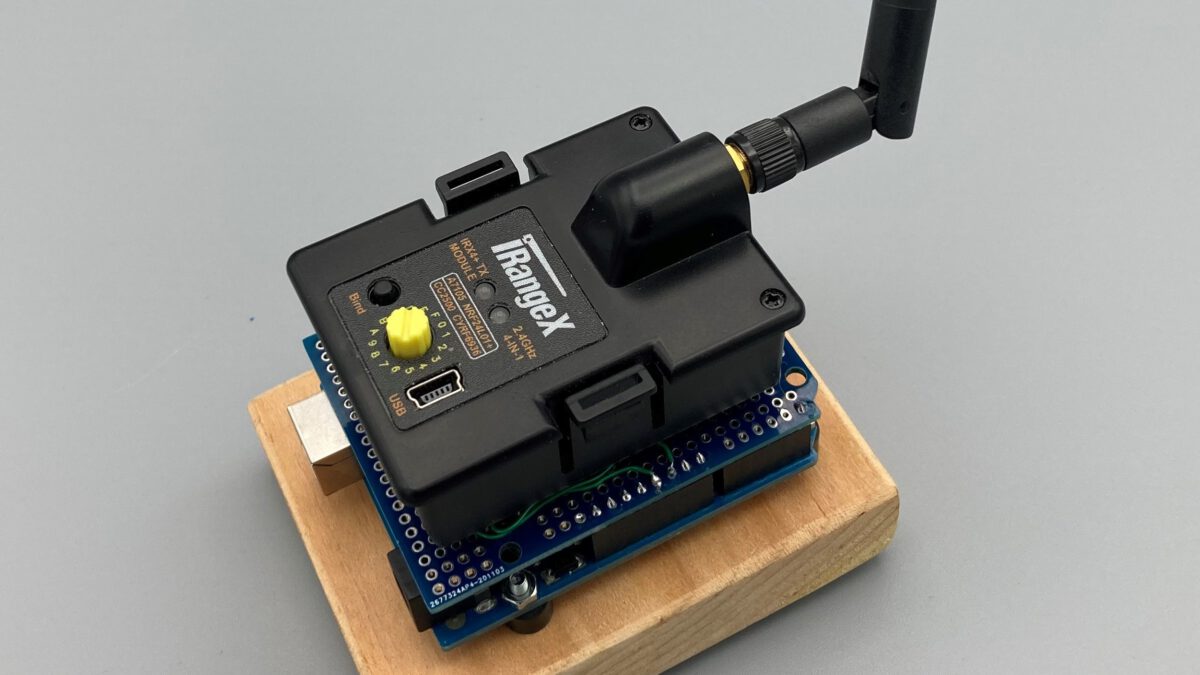
The wiring for the power supply and for the PPM signal can be found in the picture. The assembly is completed when the module is plugged in.


USB2PPM by Arduino

My previous blogs about connecting a joystick to a model remote control via USB have always used one of my PiKoders. But of course an Arduino can also take over the PPM signal generation.

To implement this idea I created an Arduino Sketch USB2PPM_by_Arduino (Open Source), which you can find on Github . The program implements a PPM encoder whose parameters and channel values are set via serial commands.

For example, you can switch the polarity of the output signal and select the number of PPM channels in the range from one to eight in order to adapt the encoder to your transmitter.

The PPM signal can be found on pin D8. To connect to the student input of your model remote control, you will then need a corresponding cable. It may also make sense to use an Arduino prototype shield that accepts a suitable socket to ensure a stable connection.

For the integration of the PPM encoder into your application, the definition of the commands and messages can be found in the header file protocol.h.

Additionally you will find the Joystick2PPM4Arduino app in the Microsoft Store with which you can connect a joystick or gamepad (DirectX-compatible) to your Arduino-based PPM-Encoder. The app connects to the Arduino Uno, Nano and Pro Micro.