Connect L298N motor driver with RC remote control receiver

Although the servo output of an RC receiver provides all the information required to control an L298N motor driver, the signal must be evaluated and recoded in a suitable manner , as the control logic of the motor driver is fundamentally different to that of an RC servo.

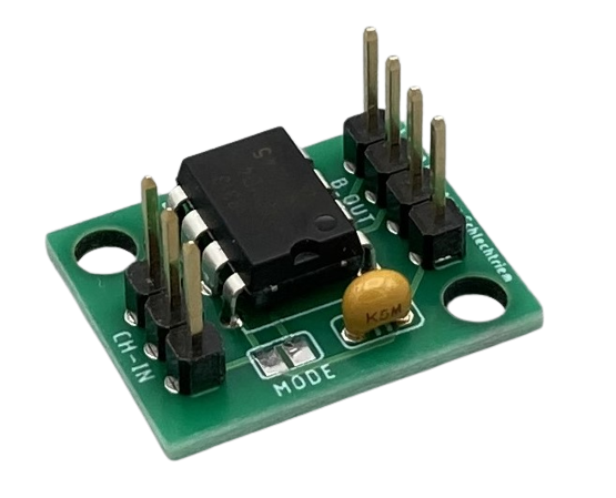
This task can be performed by the RCRX2Bridge module. This is a single-chip solution that evaluates one channel at a time and thus controls one motor of the L296 bridge. The circuit is very simple and the module is quick to assemble with the breakout board.

RCRX2Bridge Breakout Board

RCRX2Bridge supports the two common, but different control modes of L298N bridges: Models with 2/4 phases and models with two logic inputs and one speed input.

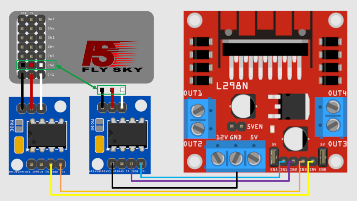
Control of bridges with two inputs

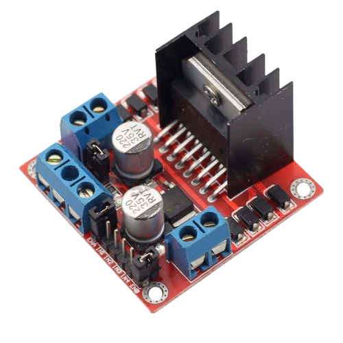
Typical L298N motor driver with two inputs per motor

The RCRX2Bridge module is connected to the receiver on the input side, as shown in the picture. The input pins of the motor driver IN1 and IN2 are connected to the output pins of the breakout board as shown in the picture. If a second motor is to be controlled, a second RCRX2Bridge module is required.

Control of bridges with three inputs

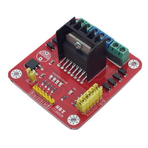
Typical L298N motor driver with three inputs

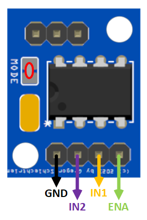
Configuration of the RCRX2Bridge for motor drivers with three inputs

For this application, the RCRX2Bridge module is configured for the changed logic using a solder bridge at “MODE” and then also connected to the receiver on the input side in this case, as shown in the article image.

The input pins of the motor driver ENA, IN1 and IN2 are connected to the output pins of the breakout board as shown in the picture. If a second motor is to be controlled, a second RCRX2Bridge module is also required here.

The kit for the breakout board with the RCRX2Bridge controller is available in the store.

Remote control with gamepad or joystick

Overview

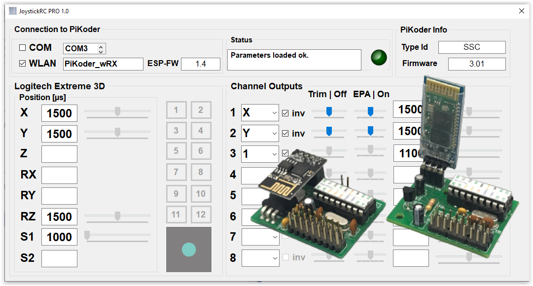
In the previous article we already presented the possibility to control up to eight servos via a USB interface using a joystick or gamepad, a PC and a PiKoder/SSC. Here is now described how a wireless model remote control can be realized with a PiKoder – receiver, the PiKoder/SSC RX. Bluetooth for command transmission.

Setup

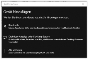
First, the PiKoder/SSC RX must be connected to the PC at the operating system level. For this purpose, you first search for new Bluetooth devices in the device control.

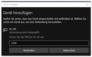
After a short time, the Bluetooth module of the receiver should be offered. The PIN is “1234”.

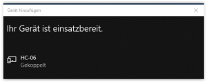
With the selection “Connect” the coupling (pairing) takes place on system level.

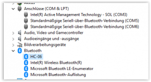
As the following view from the device manager shows, the coupling of the system also establishes two virtual serial interfaces, which we access later in the program for establishing a connection.

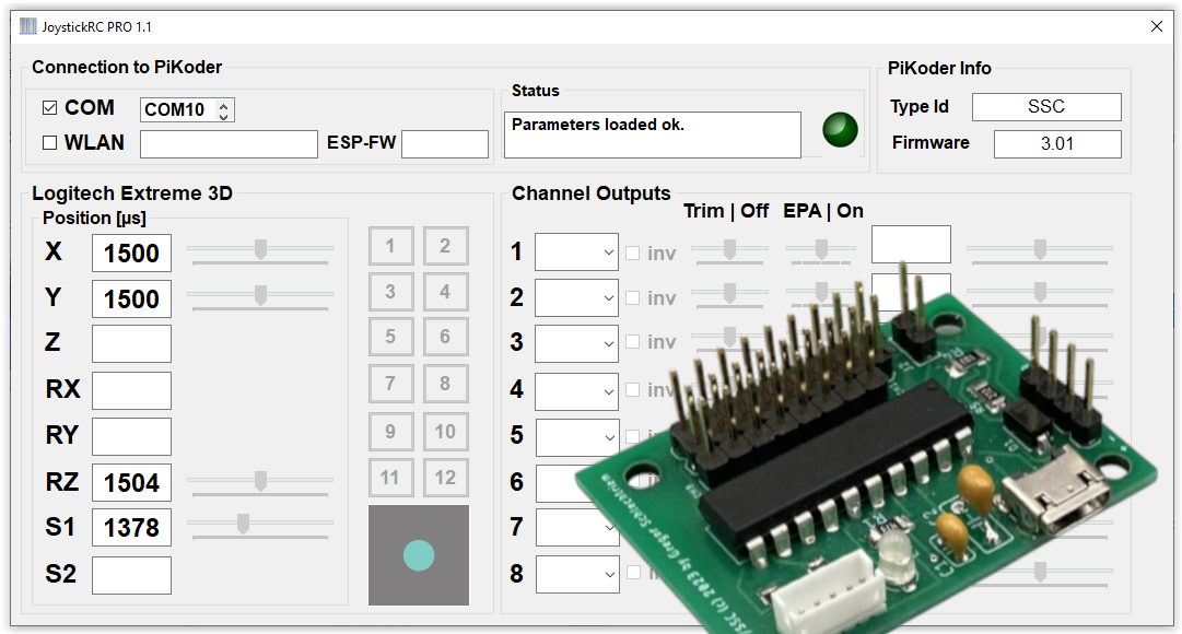
This completes the setup and the JoystickRC program can now be started as described in the previous post.

Control servos with gamepad or joystick

Overview

In the field of robotics, there is more often the need to control several servos, e.g. when realizing a robot arm. In this case, operation with a gamepad or joystick is ideal because the large number of axes / degrees of freedom enables efficient control of many channels.

This blog describes the setup to use the free Windows APP JoystickRC to control eight servos wired, e.g. for a robot arm.

The mapping of the axes and switches to the servo channels is done flexibly in the software. The actual pulse generation for the servos is done by a PiKoder Serial Servo Controller (PiKoder/SSC), which is connected to the PC via a USB adapter.

Setup

The setup is ideally done with the help of a PiKoder/SSC – development board and with a standard USB adapter. The PiKoder is supplied with power via the USB cable. Since the USB interface cannot supply enough power to control the servos, they must be supplied with an independent voltage source via the terminal strip. In order to prevent balancing currents that could damage the PC, the jumper must not be plugged into the PiKoder circuit board under any circumstances. More detailed information can be found in the PiKoder User Manual.


Connecting the USB cable to the PiKoder/SSC development board – please note that the jumper must not be plugged in.

Connecting the USB cable to the PiKoder/SSC development board – please note that the jumper must not be plugged in.

Software

The JoystickRC program is available free of charge from the Microsoft Store. You can find more instructions on how to use the program on the program’s website.

Tester for Metz MECATRONIC RC servo 190/18

I am currently working on the restoration of a Metz MECATRON ‘BABY’ radio remote control. For testing and commissioning the rowing machine, I didn’t want to switch on the entire remote control every time, so I built a simple tester.

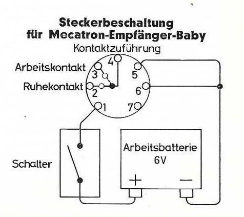
This tester reproduces the output of the receiver 191/S – a relay with a switching contact – with a corresponding button. Thus, the function of the rowing machine, which depends on the control panel used, can then be tested.

In my case, the control panel 1 is inserted; the following switch rhythm is realized according to the user manual:

  • Transmitter key pressed: Rudder left as long as button remains pressed
  • Press the transmitter button briefly (approx. 0.4 seconds), release briefly (approx. 0.4 seconds) and hold down: Rudder on the right, as long as the button is pressed the second time.
  • After letting go of the transmitter button, the rudder always goes neutral by itself.

In the setup presented here, of course, the transmitter button corresponds to the button.

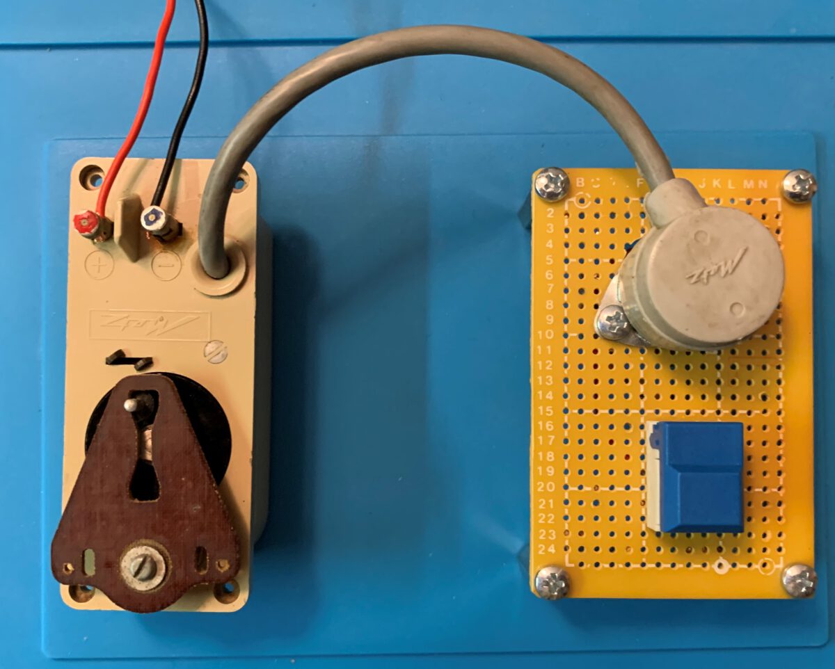
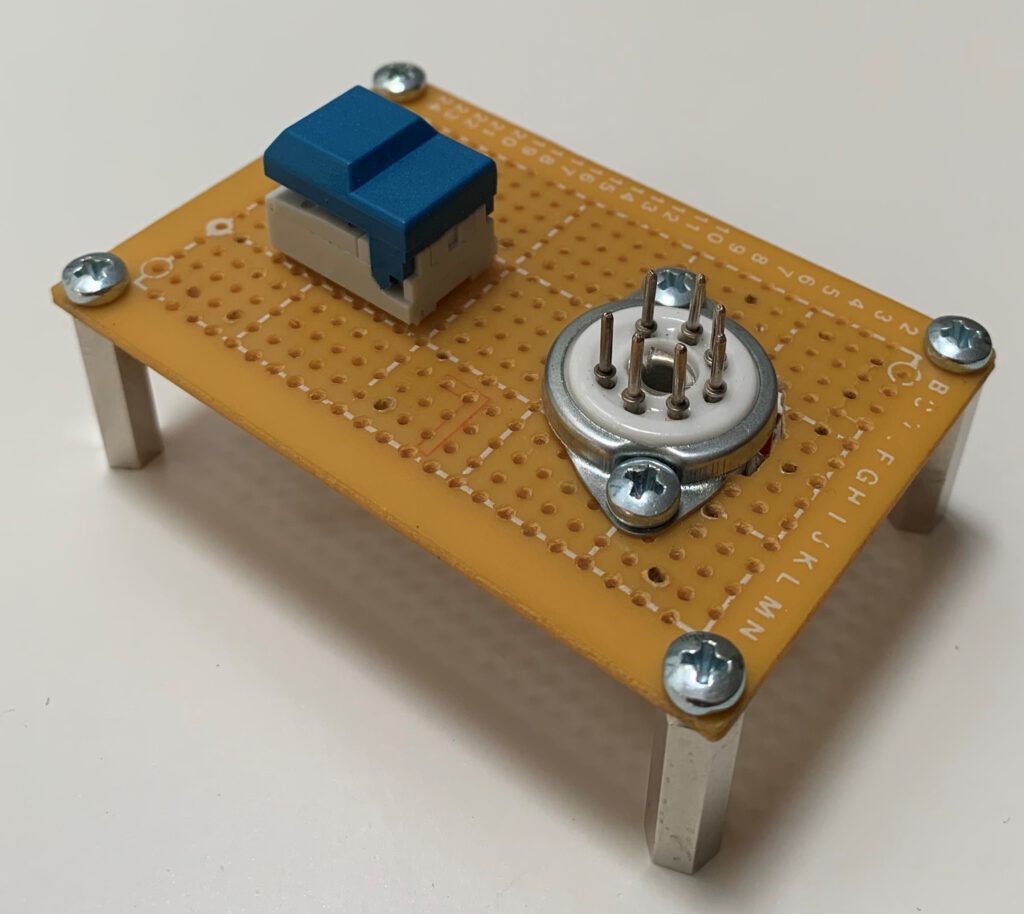
The tester can be easily mounted on a laboratory circuit board and the wiring effort is minimal. As can be seen in the picture, I realized the required 7-pin plug for connection with the rowing machine by inserting soldering nails into a 7-pin tube socket.

Digital and precise servo tester

Overview

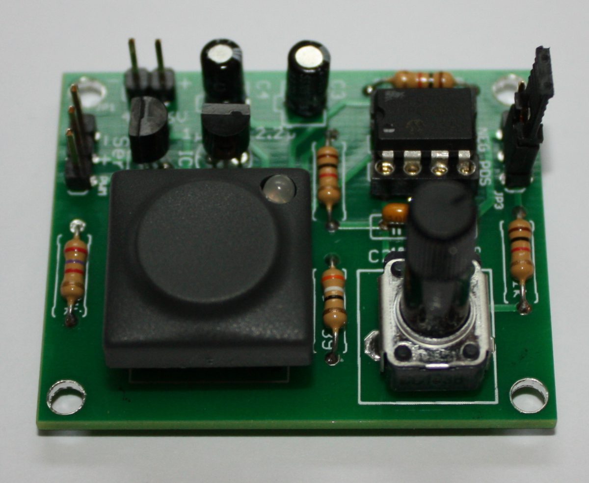
The servo tester presented here is equipped with a PIC controller to provide for very accurate pulse generation (pulse width: 1 ms – 2 ms) especially in comparison with a simpler construction with RC links. For this purpose, the internal oscillator is used, which is specified in the selected range of the supply voltage with an accuracy of 1 %.

Furthermore, the servo tester is characterized by the fact that, in contrast to other simpler digital devices, the supply voltage range is specified form 4.8 V – 6 V. With this, the servo tester can also be connected to the BEC connection of a speed controller. The polarity of the pulse for servo control can be adjusted by hardware (jumper setting).

In addition, the Servo Tester enables the use of servos for other applications, such as for rotating and panning surveillance cameras.

Circuit
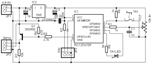
The circuit is based on the PIC12F675, which controls the servo tester. The supply voltage of the controller is lowered to 3.3 V by a corresponding controller; this ensures the highest accuracy of the internal oscillator on the one hand and the large supply voltage range of the tester on the other hand.

However, this approach requires a driver transistor Q1, which performs the level adjustment to control the servo. The supply voltage of the servo is directly looped through, so that servos or motor controllers can be tested either with the already existing battery / BEC supply by the speed controller or by means of an additional power supply (in this configuration it must be ensured that no power is provided via the servo plug).

The jumper JP3 determines the polarity of the control pulse for the servo. Please note that the LED is a bi-color LED.

Operation

The operation is simple and intuitive. The servo tester has two different operating modes: the manual mode, in which the servo is controlled by a rotary knob P1 and the neutral position can be adjusted and the exercise mode, in which the servo is continuosly moving between the end points. The change between the two operating modes is carried out by pressing the button S1. The LED will indicate the active mode of the servo tester.

After switching on, the device is in manual mode and the servo position is adjusted by rotation of the potentiometer P1. In the pulse area outside the window of 1.45 ms and 1.55 ms, the LED lights up in green. To move the servo to the neutral position, the color of the LED within the window of 1.45 – 1.55 ms changes to yellow or both colors of the LED light up and when the neutral position of 1.5 ms is reached, red is finally displayed; no button has to be pressed and both hands are free to perform adjustment work if necessary.

The Exercise Mode offers two speeds to choose from. The LED flashes red in this mode and shows which speed was selected via its flashing frequency (0.25 s corresponding to 2 x flashing/second or 15 s (correspondingly once 2 s on, then 2 s off) from final rash to final rash). The speed is switched by turning the potentiometer: if a pulse length greater than 1.5 ms is set, then the Exercise Mode is selected at high speed, otherwise the servo is controlled slowly.

Software Download

The firmware for the servo tester (Release 1.0) is freeware, which can be used without restrictions for private, non-commercial purposes according to the underlying End User License Agreement (EULA).

Servotester kit and components

In my shop you will find a complete kit for the tester.
Arduino based XBee radio control

Combine the Arduino based open source digital radio control arduinodtx with an intelligent serial servo controller such as the PiKoder/SSC, an Arduino XBee shield and an XBee module to easily build a feature rich radio control.

A transparent transmission is used, so that no adjustments to the Arduino software or the PiKoder/SSC firmware are required; the full range of functions of the remote control is available.

The setup of the transmitter including the jumper configuration is shown below – for details regarding the wiring please refer to the arduinodtx webpage.

xbee-digital-rc_404p

The configuration of the receiver comprised of an XBee breakout adapter, the PiKoder/SSC board and a dc-dc converter to generate the 3,3 Volt required by the receiver is shown below. For more details – including the programming of the XBee modules – please refer to the PiKoder/SSC Application Note #3: XBee Communication.

complete-receiver-unit

Prototyp receiver setup