This has given me the basis to process more sensors in a standard environment in the future and to plan and execute missions for the DiddyBorg.
Software installation on the Raspberry Pi (RPi)
On the RPi, first install pymavlink, the Python version of the MAVLink libraries. The easiest way to do this is with PIP:
pip install pymavlink
Then create a directory, e.g. diddy2QGC, into which you copy the Python modules diddy2QGroundControl.py and ThunderBorg3.py from the Github repository of this project. In this directory you then start the Python script later with:
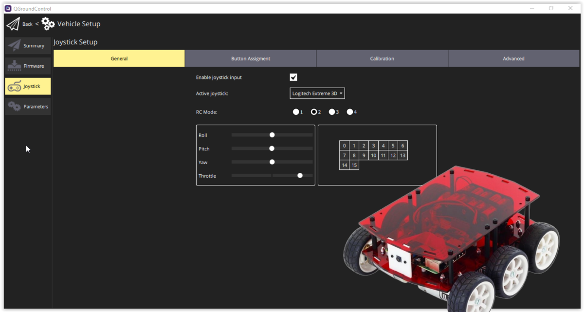
Make sure the RPi and your desktop are on the same network and run QGroundControl (QGC) and the Python script (the order is irrelevant).
The DiddyBorg sends heartbeat messages, which are recognized and answered by QGC. After exchanging a few more messages (please do not be confused by the error messages), the connection is established and you will then find the option to teach in your joystick in the vehicle settings. Please note that diddy2QGroundControl.py in mode 2 uses the roll channel for right/left control and the inverted value of the pitch channel for motor control.
In this blog I present my Windows app JoystickRC4DiddyBorg for remote control of the DiddyBorg (from PiBorg) with a joystick or gamepad.
The DiddyBorg sample programs published by the manufacturer PiBorg also include a Python remote control script with joystick, but it uses Bluetooth and therefore has a rather limited range.
The app presented here uses the existing WLAN and UDP as protocol to ensure sufficient agility of the remote control. For safety reasons, the time-out logic of the ThunderBorg motor controller is activated.
Software installation
The DiddyBorg needs a Python script JoystickRC4DiddyBorg as receiver, which you can find on github.com. In addition to the receiver program, you will also find a version of the ThunderBorg – Library for Python 3.x in the repository (the sample programs for the DiddyBorg are still based on Python 2.x).
The easiest way is to copy the two files additionally into the directory with the examples – then the script should work without further adjustments of path names.
On the PC side, install the Windows app JoystickRC4DiddyBorg of the same name, which you can get for free from the Microsoft App Store.
Operation
First start the Python script on the DiddyBorg. If you have a screen connected, then the program will log in and indicate that it is waiting for a client.
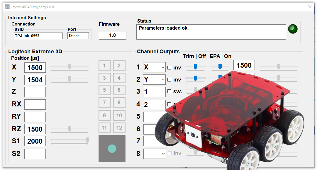
When you start the PC app, it will automatically search for a DiddyBorg with an active and compatible receiver on the local WLAN (to which both the DiddyBorg and the PC being used must be connected). If no connection can be established, a corresponding error message is displayed.
After the connection has been successfully established, the channels can be assigned to the various joystick axes and keys. Channels 3 and 4 are used as push buttons and allow for example fast / slow rotation (the function of the push buttons can be traced in the Python script).
The assignment of the channels is saved and restored at the next program start.
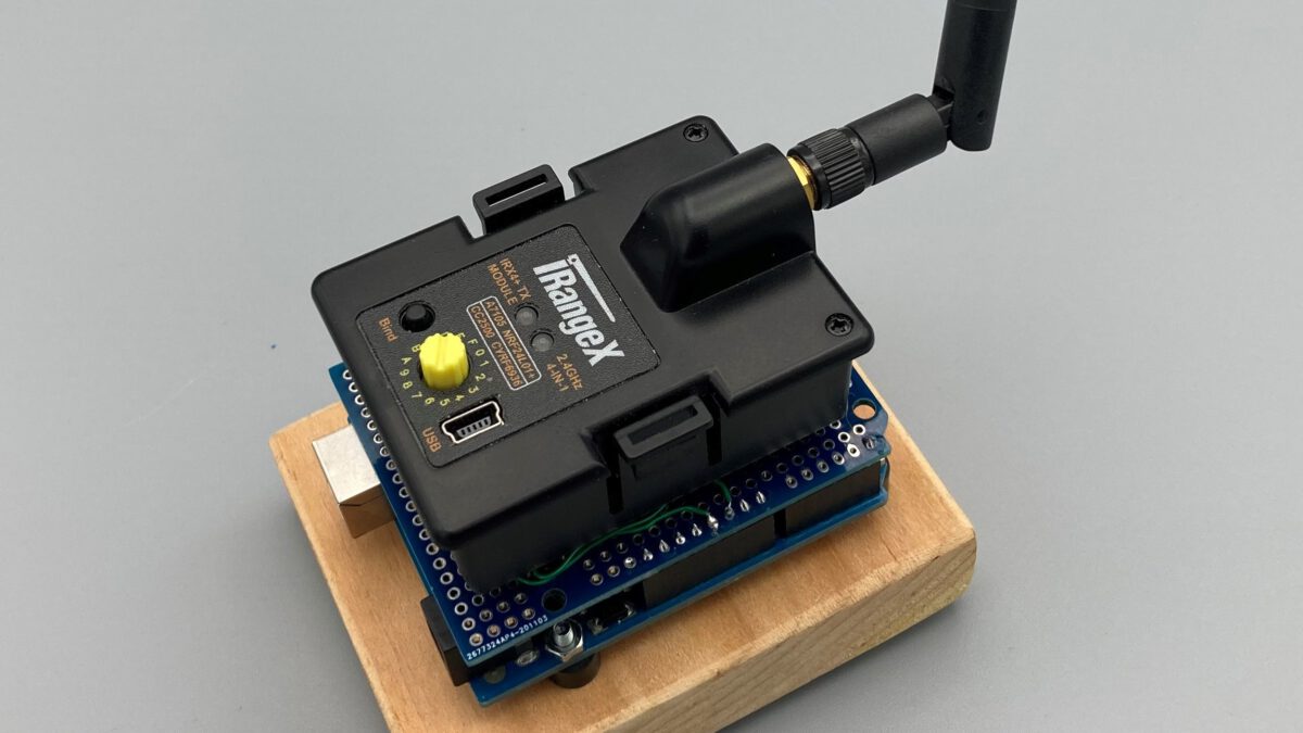
The previous blog describes the Arduino PPM encoder. Together with a multi-protocol module, you can set up a complete remote control transmitter with little additional effort.
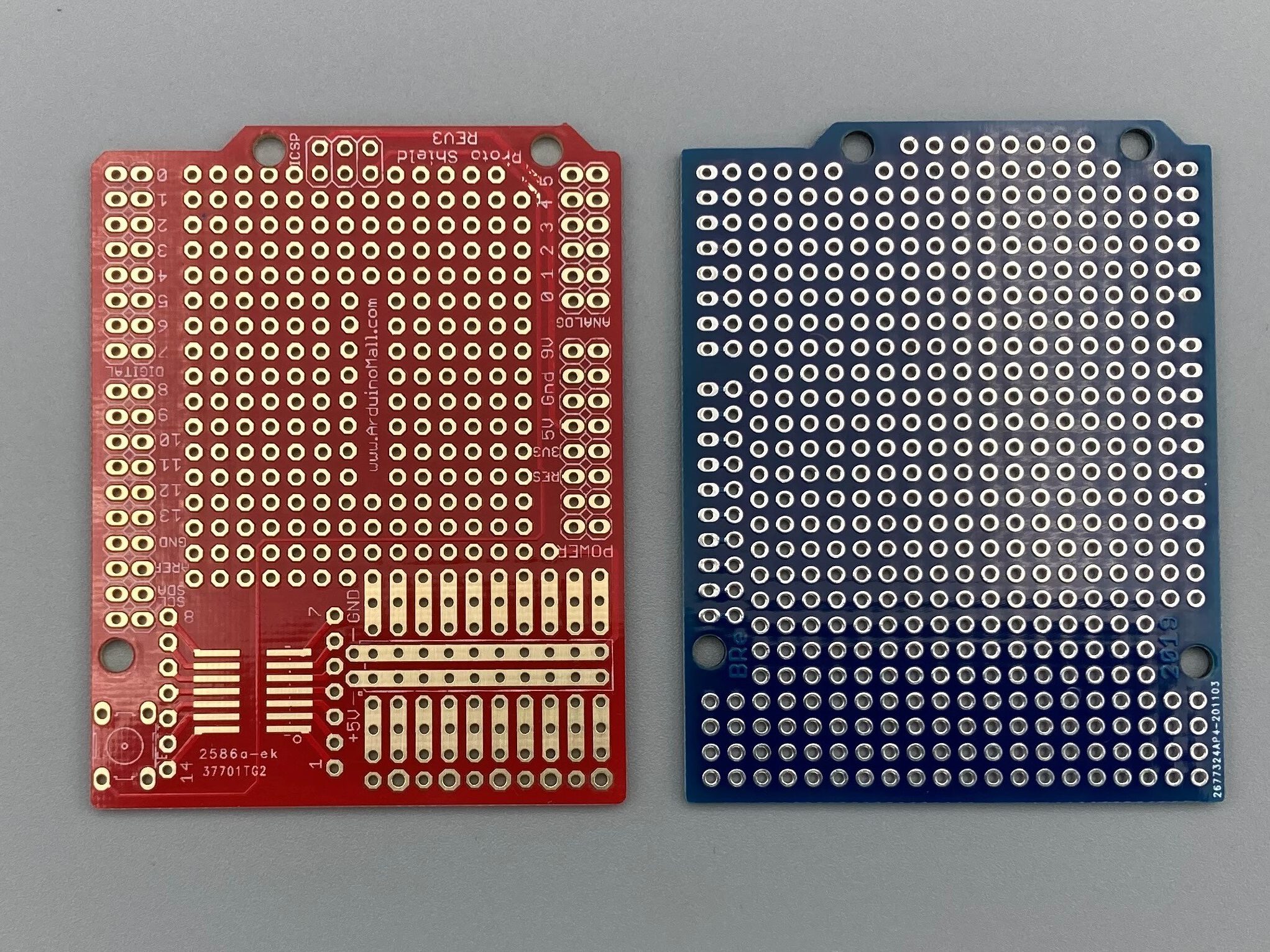
To do this, adapt the module using an Arduino prototype shield. However, not all shields are equally suitable. Some shields do not have a hole pattern in the lower right area but a specific layout like the red circuit board in the picture. But you need a prototype board with a complete breadboard like the blue circuit board.
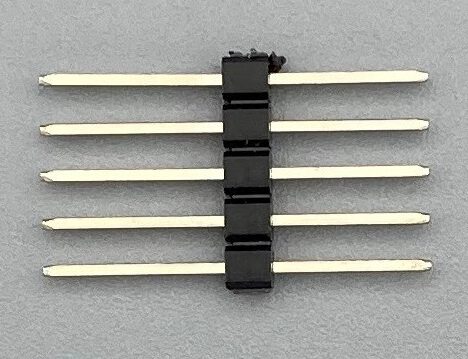
You make the electrical connection between the Arduino and the module with a five-pole pin header with extra-long pins. Insert the pin header into the socket header on the back of the module. Then position the module on the prototype shield and find the correct position for the module and the soldering points that you need to use.
To ensure a secure hold, I have also provided Velcro tape. Since this additional intermediate layer changes the height of the soldering pins again, you can only solder the pins now.
The wiring for the power supply and for the PPM signal can be found in the picture. The assembly is completed when the module is plugged in.
My previous blogs about connecting a joystick to a model remote control via USB have always used one of my PiKoders. But of course an Arduino can also take over the PPM signal generation.
To implement this idea I created an Arduino Sketch USB2PPM_by_Arduino (Open Source), which you can find on Github . The program implements a PPM encoder whose parameters and channel values are set via serial commands.
For example, you can switch the polarity of the output signal and select the number of PPM channels in the range from one to eight in order to adapt the encoder to your transmitter.
The PPM signal can be found on pin D8. To connect to the student input of your model remote control, you will then need a corresponding cable. It may also make sense to use an Arduino prototype shield that accepts a suitable socket to ensure a stable connection.
For the integration of the PPM encoder into your application, the definition of the commands and messages can be found in the header file protocol.h.
Additionally you will find the Joystick2PPM4Arduino app in the Microsoft Store with which you can connect a joystick or gamepad (DirectX-compatible) to your Arduino-based PPM-Encoder. The app connects to the Arduino Uno, Nano and Pro Micro.
The previous blog described how the originally used remote control transmitter can be replaced by an iRangeX multi-protocol module and how the entire setup can be simplified.
In this blog, an even more compact structure is described in which the USB hub, the USB2PPM PiKoder and the multi-protocol module are mechanically combined into one unit, which then only needs to be connected to the smart device and the joystick.
The following steps are required for the implementation:
Extend the USB hub cable
Modify USB2PPM PiKoder with USB connector
Realize mechanical rack
Assemble and wire modules
Extend the USB hub cable
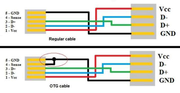
The common USB OTG hubs (on the go) usually have a very short connection cable (0.1 – 0.15 m). In practical use, this results in restrictions, since the hub must always be close to the smart device and possibly hangs in the air next to the holder and so a “rigid connection” with the PiKoder is not possible.
The extension of the connection cable is not a problem. It is only to be noted that an OTG connector with the corresponding coding (see picture) is still used as the connector, because otherwise the hub will not be recognized and will not be supplied with voltage.
The easiest way to extend the extension is to solder a piece of USB cable of the desired length to the hub board and attach the existing plug with the short cable end to the other end and fix it with shrink tubing.
Modify USB2PPM PiKoder with USB connector
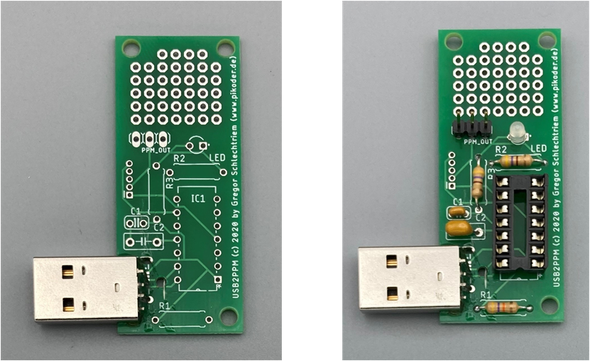
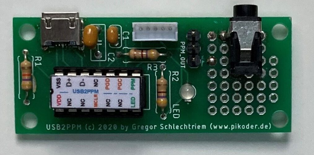
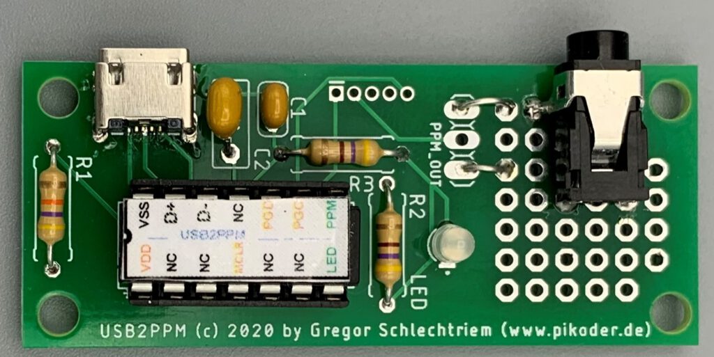
For the direct connection between the USB hub and the PiKoder, the USB2PPM requires a USB plug (see picture on the right) instead of the normal USB micro socket. So that the connector can be installed, saw the circuit board in order to then be able to push through the fastening straps. In addition, a hole is required in order to be able to wire the connection cables of the plug (see picture below).
Then stick the connector to the circuit board with two-component adhesive and equip the circuit board with the remaining components (see pictures below). Note: In the further course of the project I replaced the three-pin header with a Molex connector.
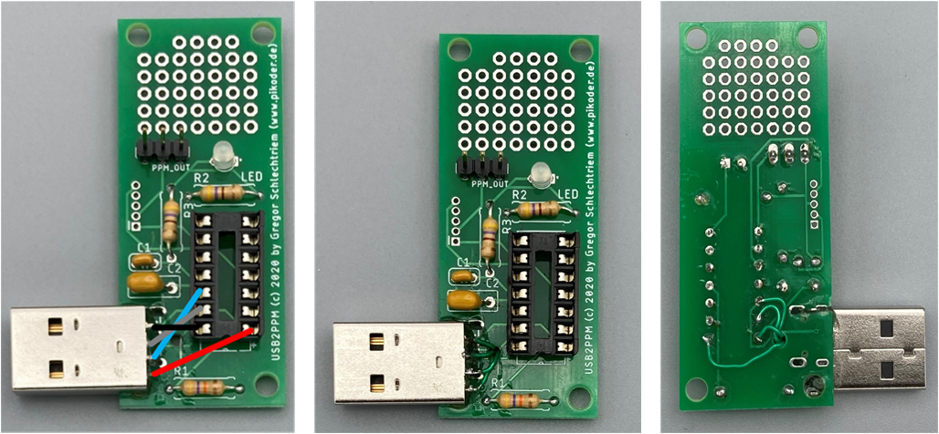
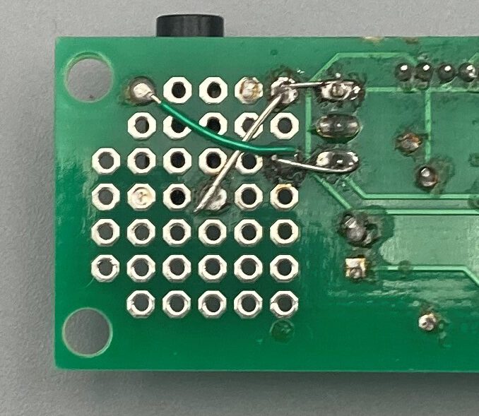
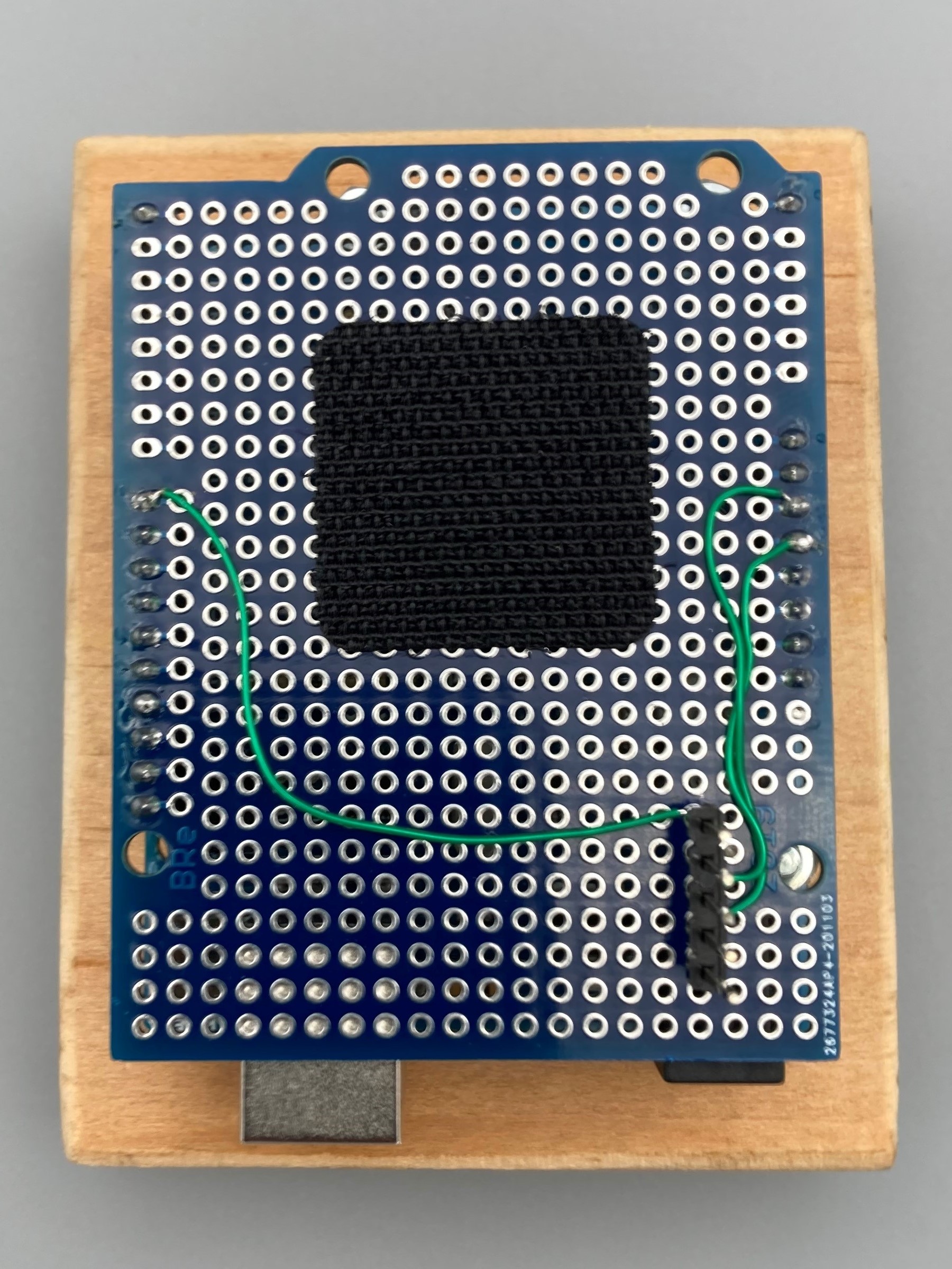
Finally connect the pins of the USB connector with the corresponding PiKoder pins; a thin, insulated wire is used for this. The following pictures show the schematic connection and then you can see the actual wiring on the underside of the circuit board.
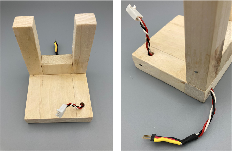
Realize mechanical rack
The subrack consists of a simple angled wooden structure. The square base plate with a side length of 85 mm accommodates the hub and the USB2PPM Pikoder. The multi-protocol module is clamped in the vertical fork. To improve the appearance of the cable routing, I drilled a corresponding channel.
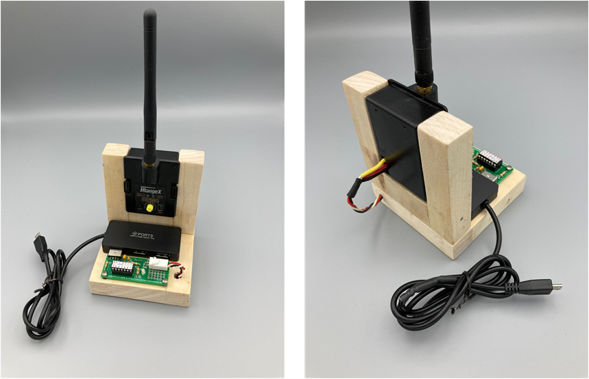
Assemble and wire modules
You can see the complete setup in the following pictures. The hub is fixed with double-sided adhesive tape, the USB2PPM PiKoder is plugged in and fixed with screws through the two front mounting holes. It is best to use some washers as spacers so that the circuit board does not bend.
With the micro USB connector, the “compact transmitter” is initially intended for connection to an Android device. With a small adapter, e.g. from Micro USB to USB C plug, the transmitter can of course be easily connected to a Surface Notebook.
In the two previous articles on model remote control with joystick, a “completely normal” remote control transmitter was used to transmit commands. The control sticks and various switches of the transmitter were not needed because the control itself is done by the joystick.
The overall structure can therefore be simplified by using a multi-protocol TX module such as the iRangeX iRX4 + instead of the complete remote control transmitter.
The module can – just like the remote control transmitter – be controlled directly via the PPM signal from the USB2PPM – PiKoder. Since the iRangeX already operates with an operating voltage of 5 volts, the power supply is also provided via the USB2PPM PiKoder and no additional battery is required.
Setup
The USB2PPM PiKoder is set up according to the instructions. Even if you have only equipped one cynch socket so far, the three-pin header can be retrofitted without any problems.
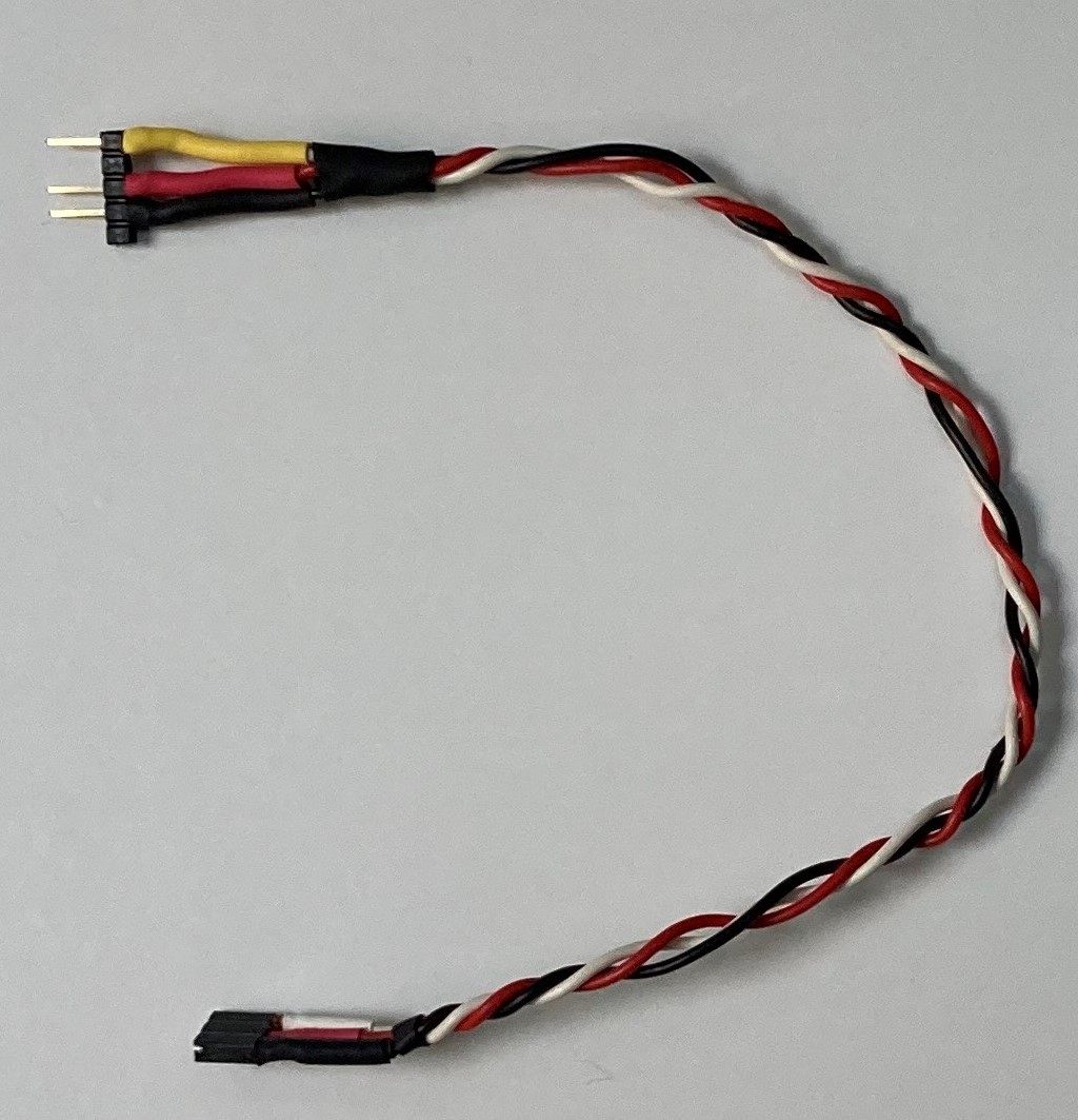
The connection between the iRX4 + module is made via a three-wire cable (Vcc, PPM and Gnd) (see picture below left). At one end of the cable there is a three-pin socket for plugging into the corresponding pin header of the USB2PPM, on the other side the five sockets of the module are adapted – you can see the pin assignment that the module expects in the picture on the right.
No further adjustments or changes are required.
And the structure described here can of course also be used in connection with a Windows notebook.
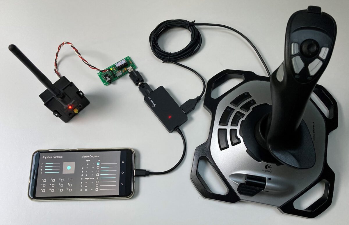
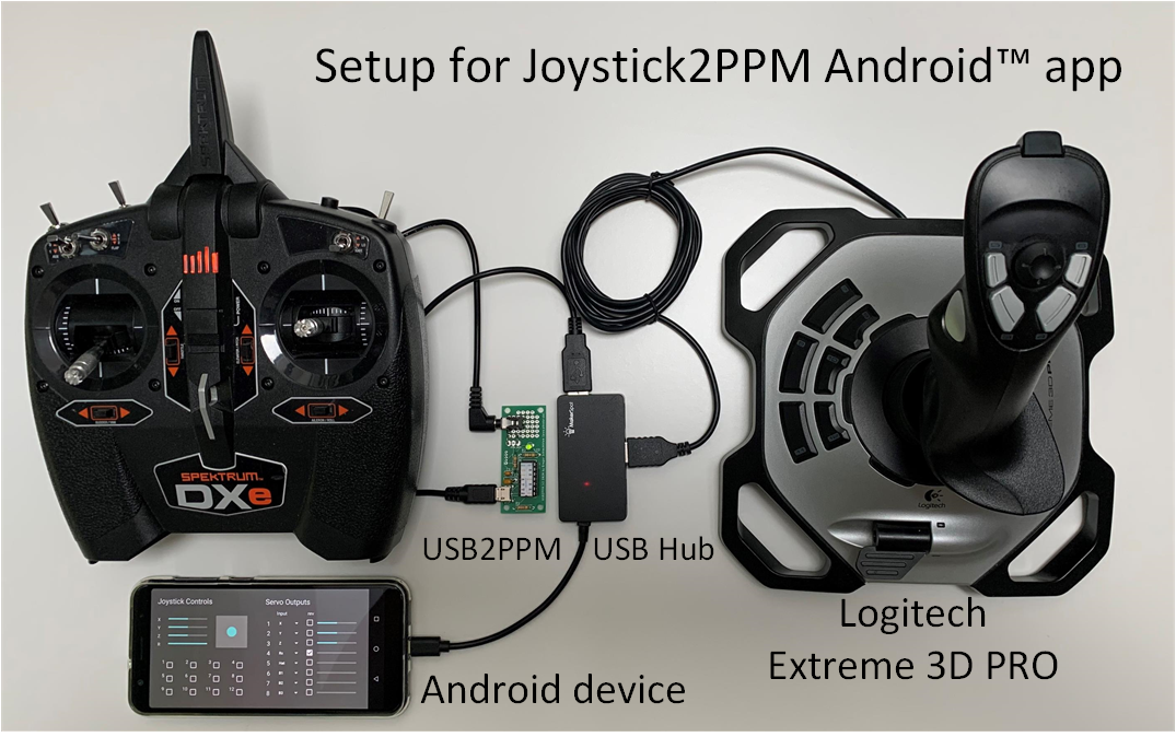
The first entry in this series used a notebook to translate the joystick inputs into commands for the USB2PPM. Alternatively, an Android (TM) smart device with a corresponding app can be used for selected joysticks.
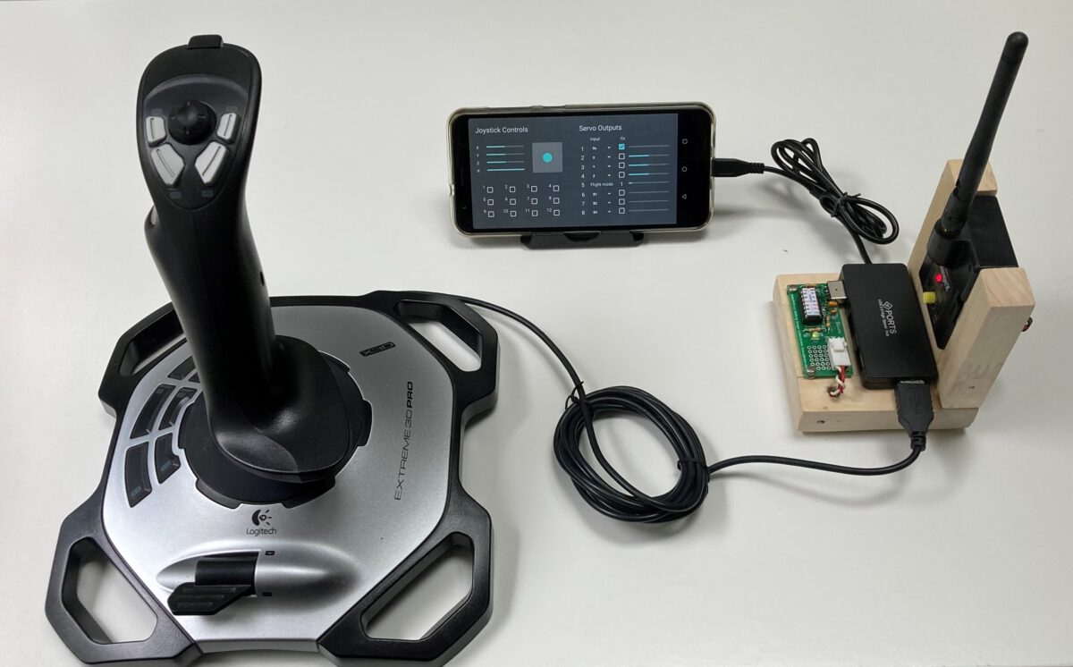
The hardware structure in the title picture is the same as the configuration in the Part 1 Except for the computer, which is replaced by the smart device, and the hub: a USB OTG hub must be used in conjunction with the smart device.
With regard to the preparation of the remote control transmitter, the same considerations for ergonomics apply and it is advisable to expand the remote control with a switch as described in Part 1.
With regard to the app itself, you can choose between the free app Joystick2PPM and a special app for quadrocopters Joystick4UAV (see below); you can find both apps in the Google Play Store.
Joystick2PPM (Android App)
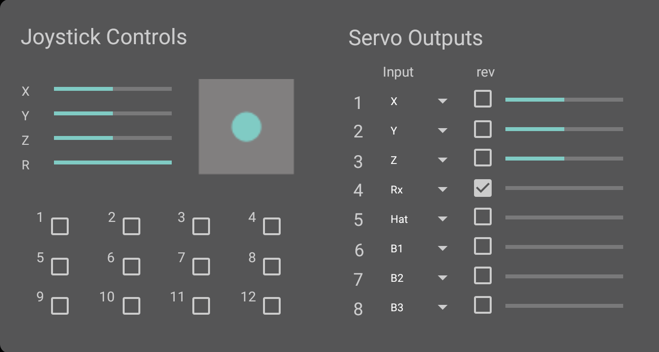
The user interface of the app largely corresponds to the Windows implementation and is intuitive and easy to understand. The joystick controls are on the left and the servo channels are mapped to the right with drop-down boxes.
The joystick and the USB2PPM are automatically recognized after starting the APP. When using the application for the first time, the user must enable access to the corresponding USB interfaces.
Please note that the app currently only supports a limited number of joysticks and other operating devices. The current list of the compatible devices can be found in the Playstore at any time.
Joystick4UAV (Android App)
The Joystick4UAV app is an advanced version of the Joystick2PPM application, which is geared towards the needs of remote control of quadrocopters or other vehicles (UGV) and boats (USV) with a flight controller.
The basic structure of the Joystick4UAV corresponds to the apps already described. The four joystick axes are mapped to the remote control channels 1-4 according to the usual assignment for flight controllers. You can of course adapt this assignment within the four channels according to your preferences. All channels can be inverted by checking the associated box.
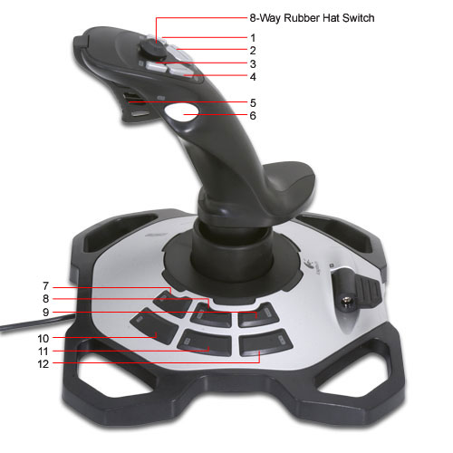
The flight mode is coded in channel 5. There are six modes available. The flight mode selection takes place by pushing the joystick buttons 7-12 (see figure below right), where button 7 sets flight mode “1” and button 12 sets flight mode “6”. The selected flight mode is displayed numerically (“1” in the picture above) and the bar corresponds to the transmitted channel value.
The remaining buttons 1-6 (button B1 .. B6 in the upper area) and the hat switch are available for special functions and can be assigned to channels 6-8 as required. If the box belonging to the channel is activated, the button behaves as a switch.
Please note that only the Logitech Extreme 3D Pro joystick is currently supported in the app.
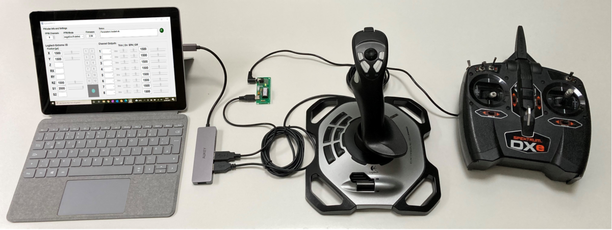
This article shows how a Spectrum DXe remote control transmitter can be used with the help of a USB2PPM adapter and a notebook to fly a quadcopter with a joystick.
The project includes the following steps:
Preparation of the remote control transmitter
Building of the USB2PPM Adapter
Download the Joystick2PPM program
Settings and commissioning
In addition to the remote control transmitter, PC or notebook with Windows 10, USB2PPM adapter and the joystick, a trainer cable is required to connect the remote control transmitter to the USB2PPM and a USB cable.
Preparation of the remote control transmitter
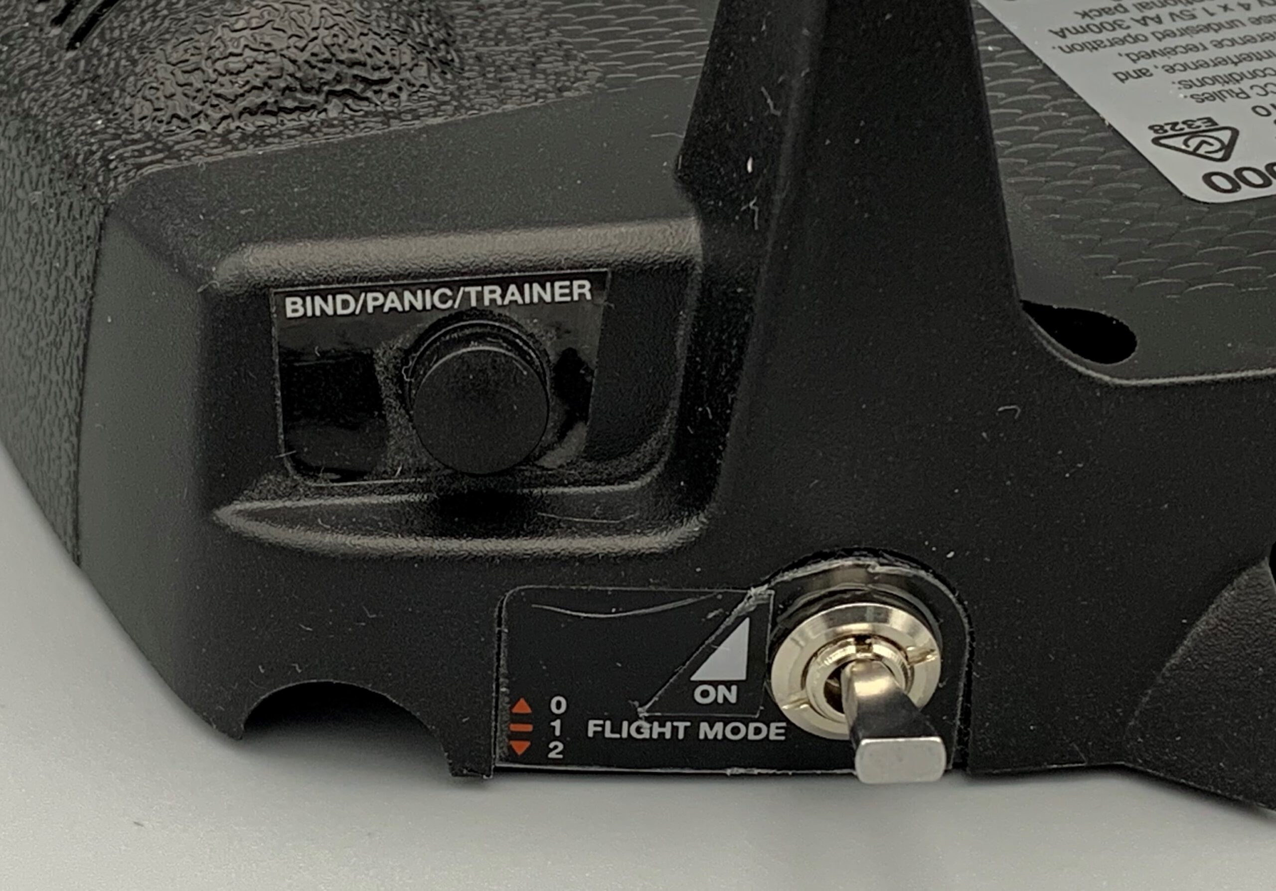
The spectrum DXe remote control transmitter is controlled by the teacher/student jack on the back of the transmitter. An external PPM signal can be fed into this jack – usually from a second transmitter, the student transmitter. The jack is a 3.5 mm standard jack and the cable connection is made via a corresponding mono-aux cable.
In order for the teacher to be able to take control quickly at any time, the student’s signal is only transmitted as long as the teacher pushes the bind / panic button. This practical implementation of the teacher-student operation naturally makes it difficult to take over the transmitter permanently, since you probably cannot or do not want to manually push the button down while flying.
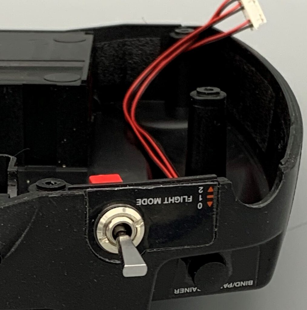
Therefore, I have installed an additional switch in my Spectrum DXe in order to be able to permanently switch the remote control transmitter to student operation. Although the installation is simple, you should only consider it if you accept the likely loss of the warranty.
Installation of the additional switch for permanent student operation
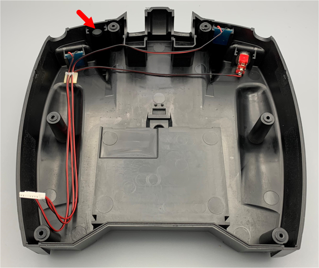
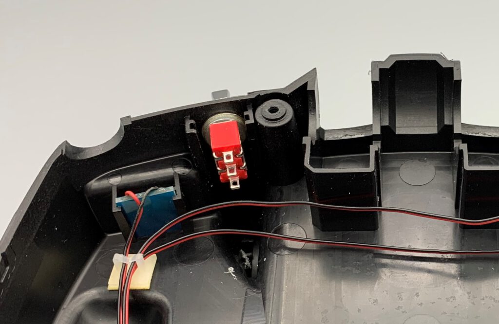
The housing is opened as described in the manual. In the back half of the transmitter housing there is already a hole at the ideal position, which is covered from the outside by a sticker (see red arrow in the picture).
Expose the hole and insert the additional switch (see details).
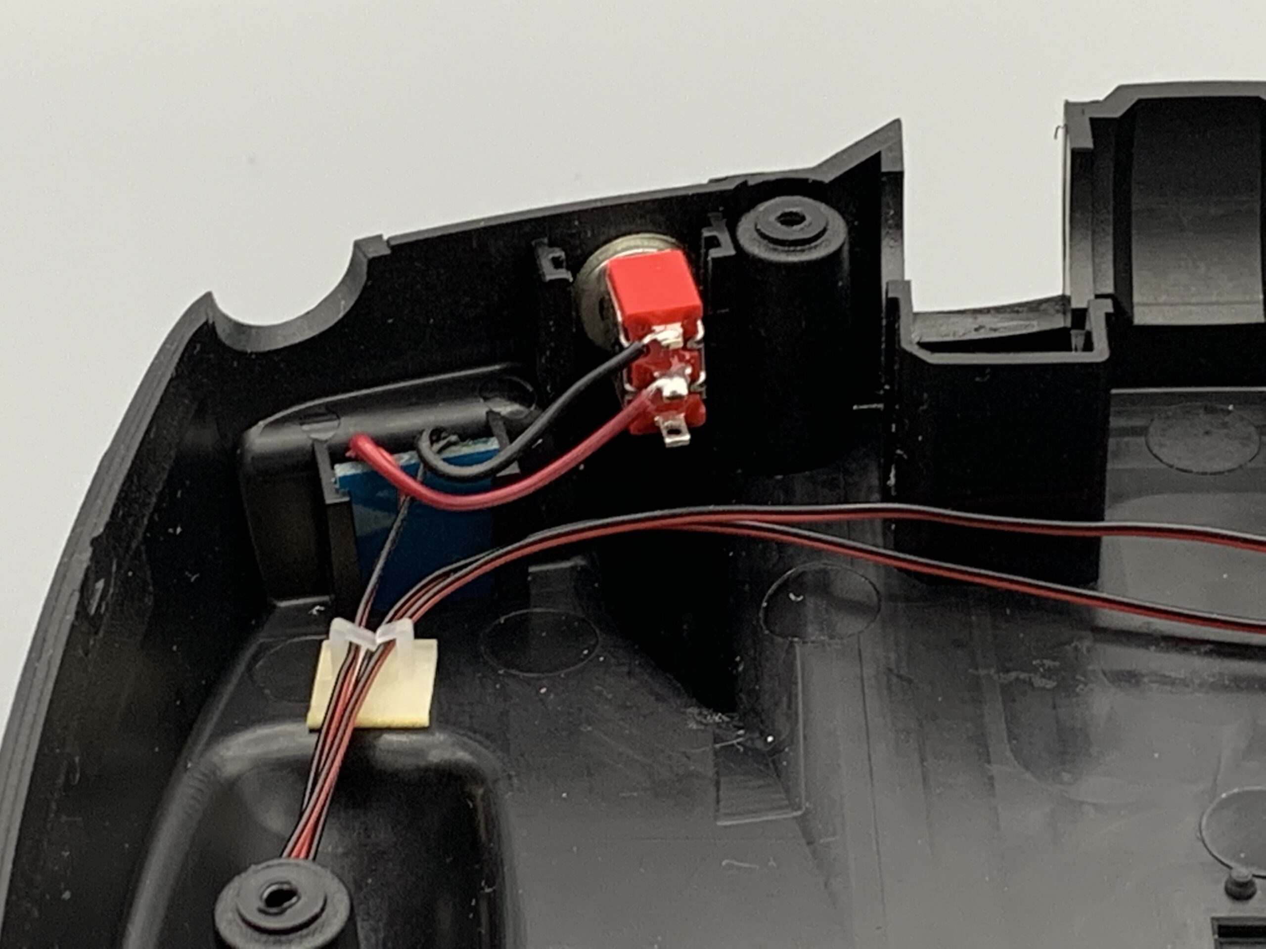
The wiring is done in such a way that the Bind/Panik/Trainerbutton is shunted (see picture). For this purpose, a short piece of wire is soldered to the small printed circuit board.
I then attached a small arrow on the outside so that I always know in which mode the transmitter would be currently (see picture).
Building of the USB2PPM Adapter
Of the USB2PPM is implemented according to the assembly instructions, but the last step is omitted (soldering in the three-pole PIN bar for the PPM signal). Instead, a 3.5 mm jack is placed in the experimental field of the printed circuit board (see pictures) to connect to the Spectrum DXe.
With this, all hardware bits and pieces for setting up the remote control are ready.
Download the Joystick2PPM program
The Joystick2PPM program takes over the evaluation of the joystick positions and the conversion into corresponding commands to the USB2PPM. This in turn generates the PPM pulse frame as an input signal for the remote control transmitter.
Now connect the USB2PPM adapter and joystick to your PC. When connected for the first time, Windows 10 will automatically install drivers and associate the adapter with a COM port.
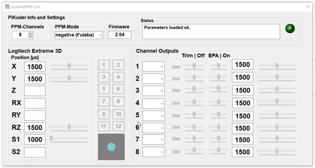
After completing the driver installation, start the Joystick2PPM program. The program automatically connects to the USB2PPM and the first joystick it finds and displays the available axes and switches on the left-hand side of the screen.
Now you can start to configure the channels for your application model-specifically.
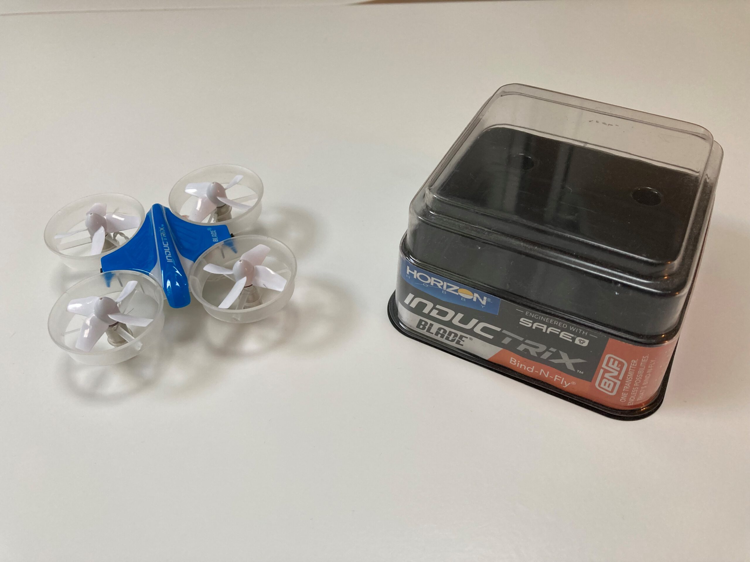
For this blog I have chosen a Blade INDUCTRIX quadrocopter as an example, but you can of course also connect other copters.
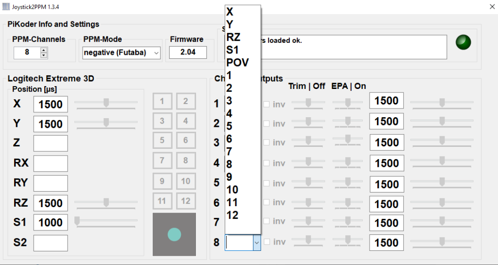
For configuration, assign the joystick controls to the individual channels of the remote control on the right-hand side (the instructions for the model may contain information on how to assign the channels). If you click on the selection box for a channel, all control elements that have not yet been assigned are displayed and you can make your selection for this channel by clicking on them.
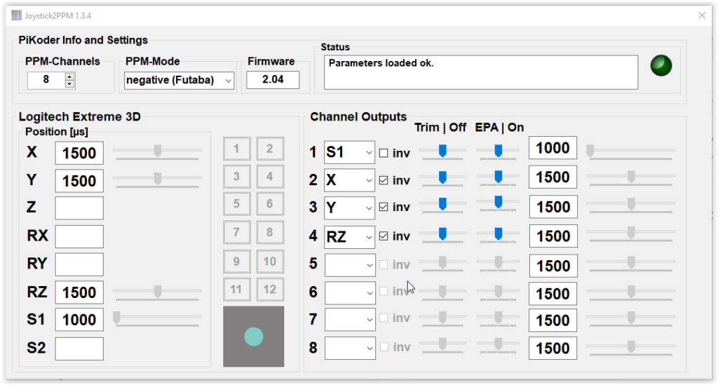
As soon as you have made an assignment, the current value for this control element is transferred to the right-hand side as the channel value. You can see the complete configuration for my application in the following screen dump.
Now turn on your transmitter and make sure that the transmitter is “paired” with the remote control model (trainer switch to “off”). Now, without turning off the remote control transmitter, connect the USB2PPM adapter using the training cable with the remote control transmitter. After turning on the trainer switch, you can remotely control your model with the joystick. If necessary, you can perform the trimming for the individual channels and a possible servo direction reversal on the PC.
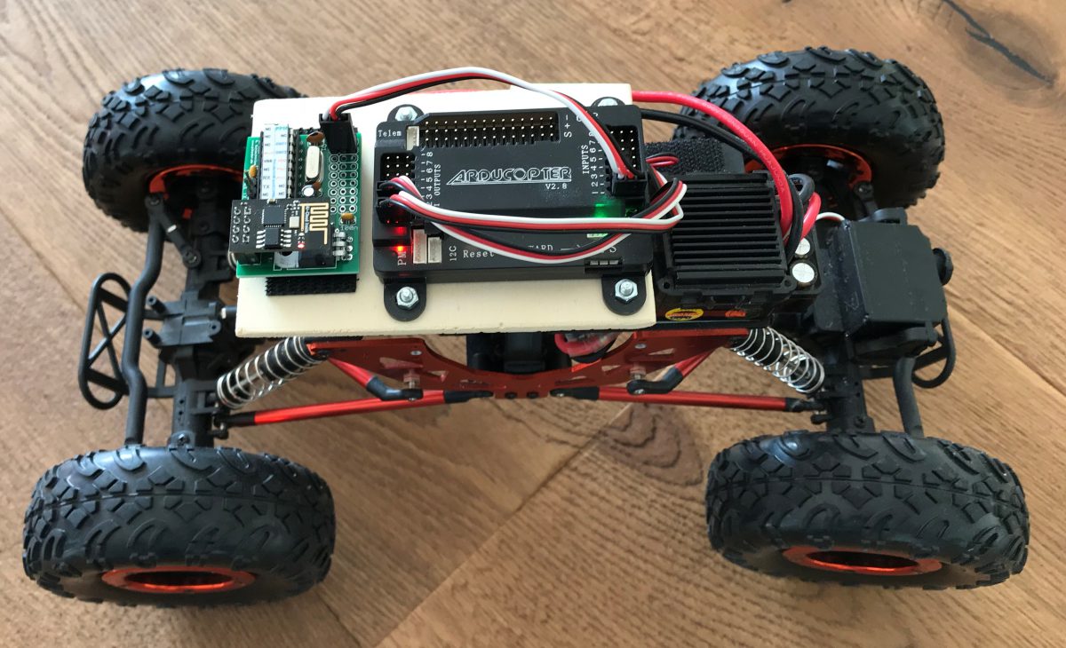
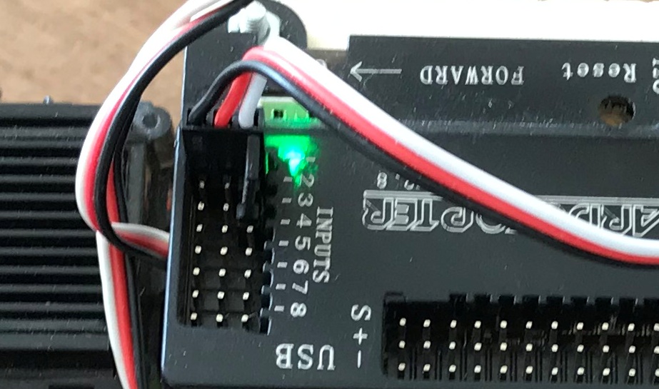
The Ardupilot Mega (APM) and other flight controllers are frequently controlled by a PPM stream rather than the parallel input per channel which I described in part 1 of this blog. The new PiKoder/PPM wRX receiver with its PPM frame output brings this capability to you. The connection between the receiver and the flight controller is reduced to a single 3 strand cable as shown in the featured image.
Description
The PiKoder/PPM wRX receiver will be controlled by the udpRC4UGV App as described in part 2 of this blog.
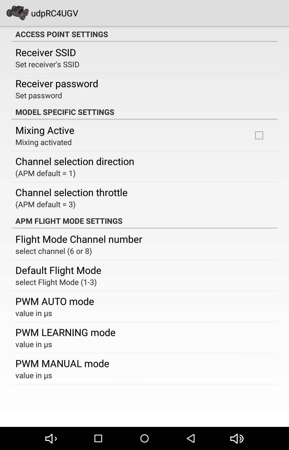
The feature set of the app has been extended to allow you to freely determine the position of the direction and throttle channel within the PPM frame through the app preferences.
To change the channel setting please select the respective preference and enter the channel number (1 .. 8). E.g. the APM Rover configuration features direction on channel 1 and throttle on channel 3.
Please note that setting the APM’s input mode from parallel to PPM requires a jumper between channel 2 and channel 3 input as shown below.
As already indicated in the previous blog on the topic “Ardupilot Mega Rover with the smartphone remote control“, now, after some further work on the topic, a new Android(TM) app “udpRC4UGV” with rover-specific functions is available. The most important enhancements are the selection of the flight mode and the toggling of channel 7 making a number of APM special functions available.
Description
As outlined in the previous blog a PiKoder/SSC wRX receiver replaces the standard RC receiver in the rover. The smartphone RC uses WLAN for command transmission: the PiKoder does offer an access point (AP) to which the smartphone will connect.
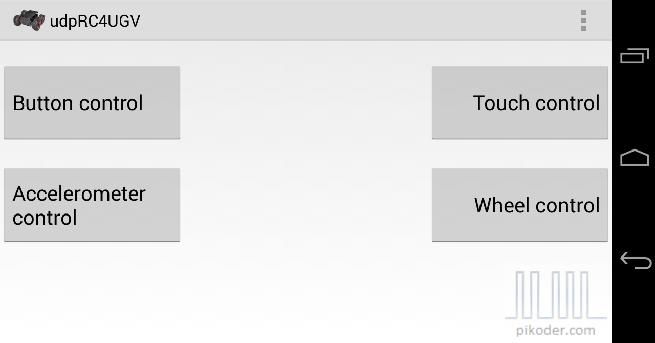
The remote control app offers a variety of user interfaces: from simple key control to a virtual joystick to an accelerometer-based option.
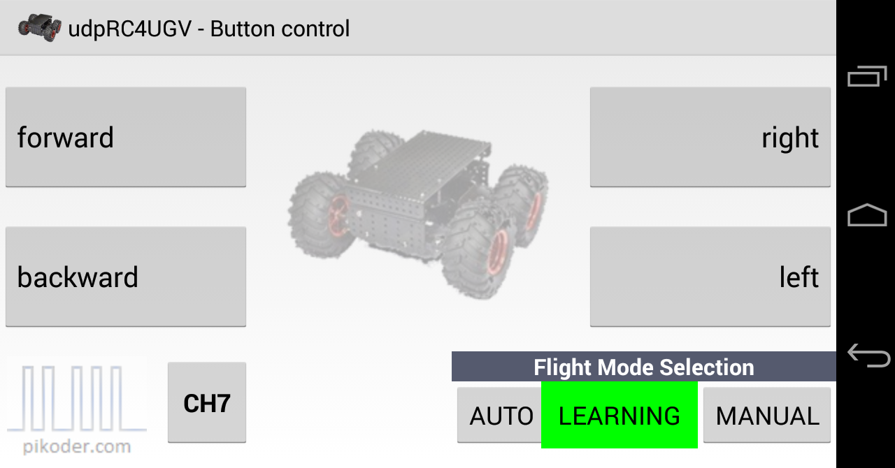
In addition to the general controls for remote control, each user interface also offers the possibility to choose the flight mode. In addition, channel 7 can be triggered via the “CH7” button (for example, in LEARNING mode, the current position is saved as a waypoint).
The app is available free of charge from the Google Play Store. The User Manual can be downloaded from the PiKoder website; it describes not only the program operation in detail, but also the hardware setup.
Einwilligung verwalten
Um dir ein optimales Erlebnis zu bieten, verwenden wir Technologien wie Cookies, um Geräteinformationen zu speichern und/oder darauf zuzugreifen. Wenn du diesen Technologien zustimmst, können wir Daten wie das Surfverhalten oder eindeutige IDs auf dieser Website verarbeiten. Wenn du deine Einwilligung nicht erteilst oder zurückziehst, können bestimmte Merkmale und Funktionen beeinträchtigt werden.
Funktional
Always active
Die technische Speicherung oder der Zugang ist unbedingt erforderlich für den rechtmäßigen Zweck, die Nutzung eines bestimmten Dienstes zu ermöglichen, der vom Teilnehmer oder Nutzer ausdrücklich gewünscht wird, oder für den alleinigen Zweck, die Übertragung einer Nachricht über ein elektronisches Kommunikationsnetz durchzuführen.
Präferenzen
Die technische Speicherung oder der Zugriff ist für den rechtmäßigen Zweck der Speicherung von Präferenzen erforderlich, die nicht vom Abonnenten oder Benutzer angefordert wurden.
Statistiken
Die technische Speicherung oder der Zugriff, der ausschließlich zu statistischen Zwecken erfolgt.Die technische Speicherung oder der Zugriff, der ausschließlich zu anonymen statistischen Zwecken verwendet wird. Ohne eine Vorladung, die freiwillige Zustimmung deines Internetdienstanbieters oder zusätzliche Aufzeichnungen von Dritten können die zu diesem Zweck gespeicherten oder abgerufenen Informationen allein in der Regel nicht dazu verwendet werden, dich zu identifizieren.
Marketing
Die technische Speicherung oder der Zugriff ist erforderlich, um Nutzerprofile zu erstellen, um Werbung zu versenden oder um den Nutzer auf einer Website oder über mehrere Websites hinweg zu ähnlichen Marketingzwecken zu verfolgen.
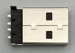 For the direct connection between the USB hub and the PiKoder, the USB2PPM requires a USB plug (see picture on the right) instead of the normal USB micro socket. So that the connector can be installed, saw the circuit board in order to then be able to push through the fastening straps. In addition, a hole is required in order to be able to wire the connection cables of the plug (see picture below).