Overview
If you would search the internet you will find quite some DIY pic programmers. However, those designs often either require a true serial or parallel port instead of an easily available USB port or are designed around a pre-programmed controller assuming access to a programmer.
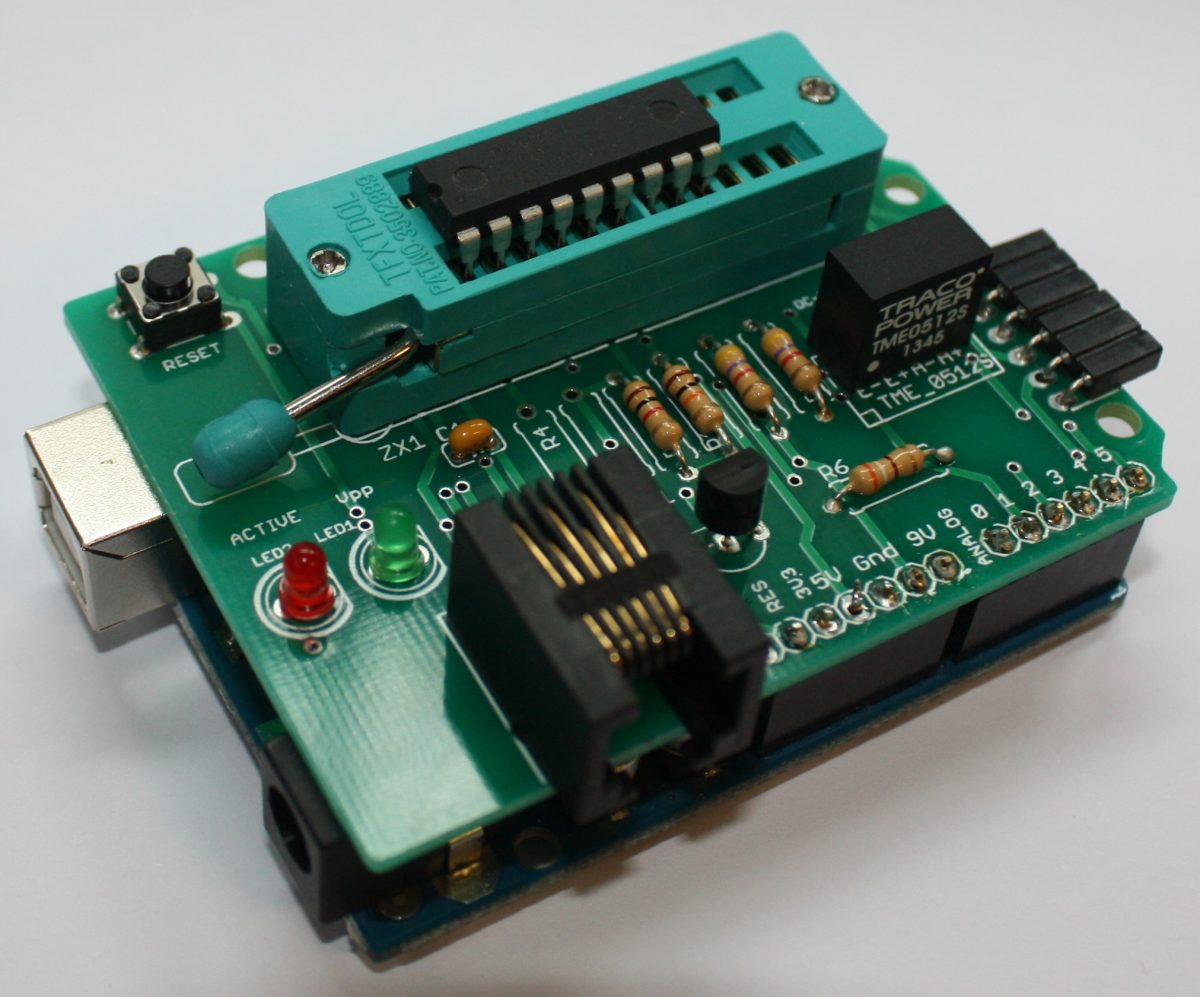
A compelling alternative would be the use of an Arduino as in the ArdPicProg. Load the Arduino sketch, the host program and add a prototype shield with a very limited number of additional components to build your pic programmer. This programmer features also a ICD connector and an RJ-11 jack (ICD2) interface. The complete project including hard- and software is open source and is released under the GNU General Public License Version 3. You can build your own ArdPicProg by using the especially designed PCB.
The complete setup and the application of the ArdPicProg is described in more detail in the User’s Guide.
Host-Software for ArdPicProg
For programming a pic controller a host software would be required. You can select between two options: the terminal program “Ardpicprog” or the “Arduino Pic Programmer” (ArdPicProgHost) with a Windows based graphical user interface. The source code for both programs is Open Source and would be available for download on github.
Arduino Pic Programmer (ArdPicProgHost)
This windows application offers a modern and intuitive way of programming a pic controller.
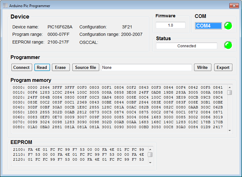
Controllers which are supported by the Arduino Pic programmer can be read, erased, and written. The user interface and the program options are also described in the User’s Guide.
ArdPicProgHost was programmed with Microsoft VB2010 Express and is released under a GNU General Public License Version 3. The source code is provided through a github repository. The executable (Release 0.2.7) can be downloaded here:
The software does not require any installation. After downloading and unzipping the program can be executed right away.
PicProgHost (terminal program)
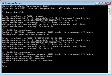
You could also employ the host application “PicProgHost” for programming pic controllers which offers a terminal interface. The application is based on the open source Ardpicprog host software you would find on the ArdpicProg project pages. These pages also provide for a suitable documentation of the program operation.
The original source code has been migrated to a Qt 5 environment and the most recent version is now capable of handling COM ports > 9. The can be downloaded here:>
The source code is available on github. The line commands are fully backwards compatible to Ardpicprog – therefore please refer to the ArdPicProg project pages for more information.
There is no program installation required. The user interface is also described in the User’s Guide.
Arduino sketch “ProgramPic”
The “ProgramPic” Sketch which is required for using the Arduino ArdPicProg shield is released under a GNU General Public License Version 3 The sketch is provided through the ProgramPic github repository.
ArdPicProg printed circuit board
The ArdPicProg PCB is available in the shop.
In the first: please excuse my bad english, I’m an old native speaking german (50++).
I’ve made my own shield using ardpicprog ICSP compounding with an ISP-Header for AVR-Programming and a very proprietary programmer for AT89S51/52, AT89S8253, AT89S4051.
So thanks a lot for the great work in ardpicprog, so I have a (very low cost) shield for 3 kinds of MCU family.
But there is one thind, that I don’t understand:
Why are you using an expensive DC-DC Converter TME512 ? It is simple to create +12V using a PWM clock from Arduino together with a switched coil.
Function in Arduino sketch:
void pwm25k_init(void)
{
TCCR1A= 0; TCCR1B= 0;
TCNT1= 0;
// Nichtinverter PWM Kanal A und B; Modus 10h: Phase korrekt
TCCR1A= _BV(COM1A1) | _BV(COM1B1) | _BV(WGM11);
// Prescaler= 1
TCCR1B= _BV(WGM13) | _BV(CS10);
// Werte von 0 bis 320 werden vom PW interpretiert
ICR1= 320;
}
void pwm25k_set(unsigned int value)
{
OCR1A= value;
}
————————
// Code in setup()
// generate a 25 kHz clock output for step-up converter
pinMode(PIN_PWM25K, OUTPUT);
pwm25k_init();
pwm25k_set(55); // 25kHz using 220uF capacitor to buffer +12V
———————–
Nice greetings,
Ralph
Great idea which simply did not occur to me when I designed the board. Thank you very much for sharing!
Dear Ralph
First of all wish you and your family a merry christmas and HNY 2019.I am new to arduino, can you please help me that where to define these function in sketch and where to call these in loop function to produce the 12v for vpp, where to define the pin to which the base of the bc549 will be connected . I want to make one such programmer for me.
thanks in advance
regards.