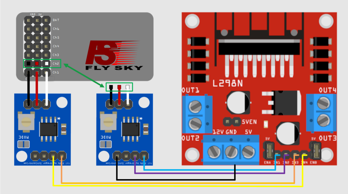
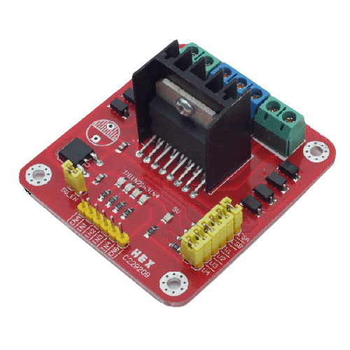
Although the servo output of an RC receiver provides all the information required to control an L298N or IBT-4 motor driver, the signal must be appropriately decoded and re-encoded, since the control logic of a motor driver is fundamentally different from that of an RC servo.
This task can be performed by the RCRX2Bridge II module.. This is a single-chip solution that processes one channel and uses it to control one motor via an L296 bridge or an IBT-4 motor driver. The device expects a standard PWM signal for analog servos, with a pulse width ranging from 1,000 µs to 2,000 µs, a neutral position at 1,500 µs, and a repetition period of approximately 20 ms.
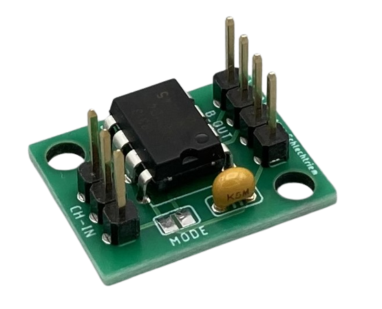
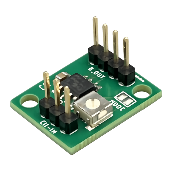
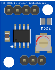 With the new version of the module, the width of the range in which the motor is not driven — the hysteresis — can now be adjusted via a trimmer on the circuit board (see image). This now also allows support for simpler remote control receivers whose pulse widths fluctuate by more than 5 µs in the neutral position (up to a maximum of 100 µs with the trimmer turned fully to the left).
The circuit is very simple, and the breakout board already comes populated with all SMD components, so only the pin headers still need to be soldered. The assembly is both electrically and mechanically backward compatible with the first version of the RCRX2Bridge.
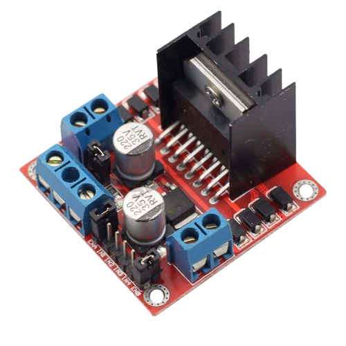
RCRX2Bridge II continues to support the two common but different control schemes used by L298N bridges: models with 2/4-phase control and models with two logic inputs and one speed input, as well as the IBT-4 motor driver.
Control of bridges with two inputs
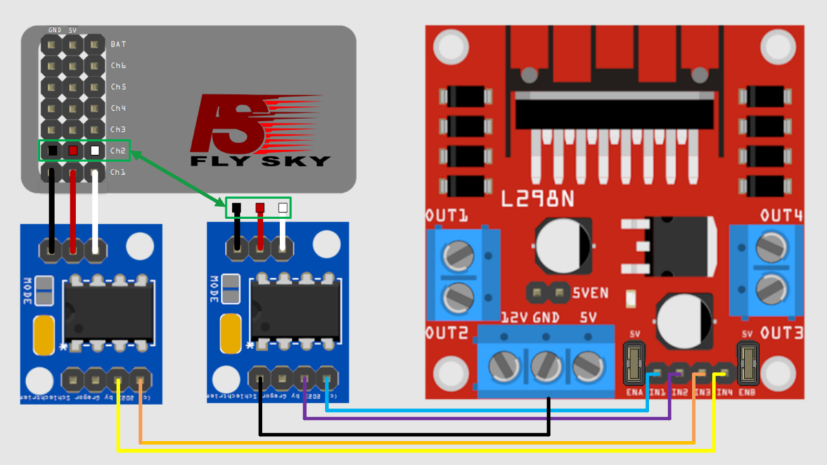
The RCRX2Bridge II module is connected to the receiver on the input side, as shown in the featured image. The input pins of the motor driver IN1 and IN2 are connected to the output pins of the breakout board as shown in the featured image. If a second motor is to be controlled, then a second RCRX2Bridge II -module is required..
Control of bridges with three inputs
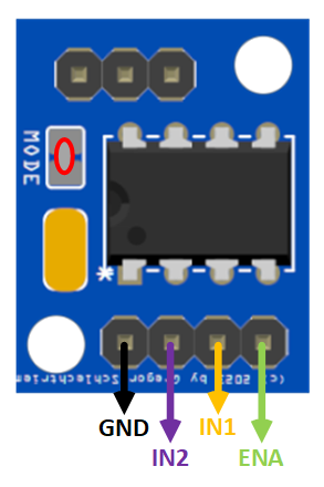
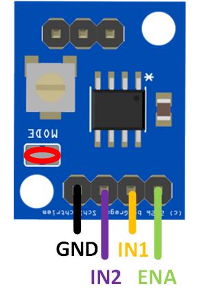 For this application, the RCRX2Bridge II module is configured for the changed logic using a solder bridge at “MODE” and then also connected to the receiver on the input side, as shown in the featured image.
The input pins of the motor driver ENA, IN1, and IN2 are connected to the output pins of the breakout board as shown in the image to the right. If a second motor is to be controlled, then a second RCRX2Bridge II -module is required.
Controlling the IBT-4 Motor Driver
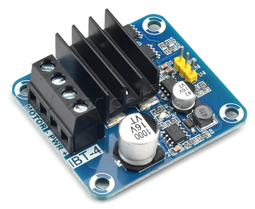
The IBT-4 motor driver is controlled via the two inputs IN1 and IN2. The required signals are identical to those used for the bridge with two inputs, so no solder bridge or any other modification is required (see above).
The required connections are shown in the following diagram:
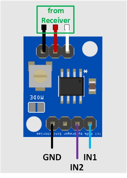
IBT-4 Connection Diagram
IBT-4 Connection Diagram
The kit for the breakout board with the RCRX2Bridge II controller is available in the store.