RC with your web browser – more intuitive and more agile

In previous blogs related to RC with a web browser I presented solutions which were suited for simple and none time critical applications due to the user interface and the system response time.

The initial concept of a button based user control was relatively slow because the web page had to be re-transmitted and rebuild on the client side after each user interaction.

The improved “joystick”-based interface was already deploying AJAX to improve the system agility. However, in order to initiate a command you would have to touch the screen and to stop the movement you would have to touch the screen at another location which is not very intuitive. You would probably expect a movement to last as long as you touch the screen.

The latest version of httpRC presented here does address both requirements based on a button based UI: a command is executed only as long as you touch it in a very agile way.

The source code for the ESP8266-01 is provided through github and the programming itself can be done via the programming adapter described earlier.

Additional information regarding the receiver kit you would find on the respective PiKoder page.

Arduino WLAN RC Transmitter

Der Open Source Arduino Sketch arduinodtx implementiert die Bedieneroberfläche und die Bedienelemente für einen leistungsfähigen Modellfernsteuerungssender mit einem seriellen Kommandoausgang (PiKoder/SSC kompatibel). Für die Kommandoübertragung zum PiKoder wird ein transparenter serieller Kommunikationskanal benötigt.

Soll WLAN als Übertragungsweg genutzt werden, dann kann ein solcher Kanal senderseitig mit einem ESP8266-01 Modul realisiert werden; als Empfänger kommt ein PiKoder/SSC wRX zum Einsatz.

In diesem Fall werden neben den Basiskomponenten wie Steuerknüppeln, Schalter, etc., die zum Aufbau des arduinodtx-basierten Fernsteuersenders erforderlich sind, ein Logic Level Umsetzer von 5 auf 3,3 Volt, zwei Jumper zur Umschaltung der seriellen Kommunikationsschnittstelle (UART-Multiplexer) und ein ESP8266-01 Modul benötigt wie im Beitragsbild dargestellt. Die Verdrahtung entnehmen Sie dem folgenden Schaltbild (die Signale mit gleicher Bezeichnung müssen verbunden werden, Signale in blauer Schrift sind mit den entsprechenden Arduino-Signalen zu verbinden):

Der Aufbau ist relativ einfach und sollte problemlos auf einem Prototyp-Board erfolgen können.  

Im nächsten Schritt ist der ESP8266-01 als Access Point mit seriellem Ausgang zu programmieren – die Beschreibung hierzu finden Sie im Blog ESP8266-01 Sketch für den PiKoder/SSC wRX. Wollen Sie den ESP8266-01 im “eingesetzten Zustand” programmieren, dann müssen Sie die dargestellte Schaltung um einen Programmierteil erweitern:

Bitte beachten Sie auch die Jumperstellung für D0/D1. Zusätzlich sollte bei jeder direkten Kommunikation mit dem ESP8266-01 der Arduino “stillgelegt” werden (RESET Leitung auf GND legen), so dass die Datenübertragung nicht gestört wird.

Mit dem erfolgreichen Abschluss der Programmierung des ESP8266-01, dem Umstecken der Jumper, Aufwecken des Arduino und einem Reboot ist die Modellfernsteuerung betriebsbereit. 


Radio control with your webbrowser

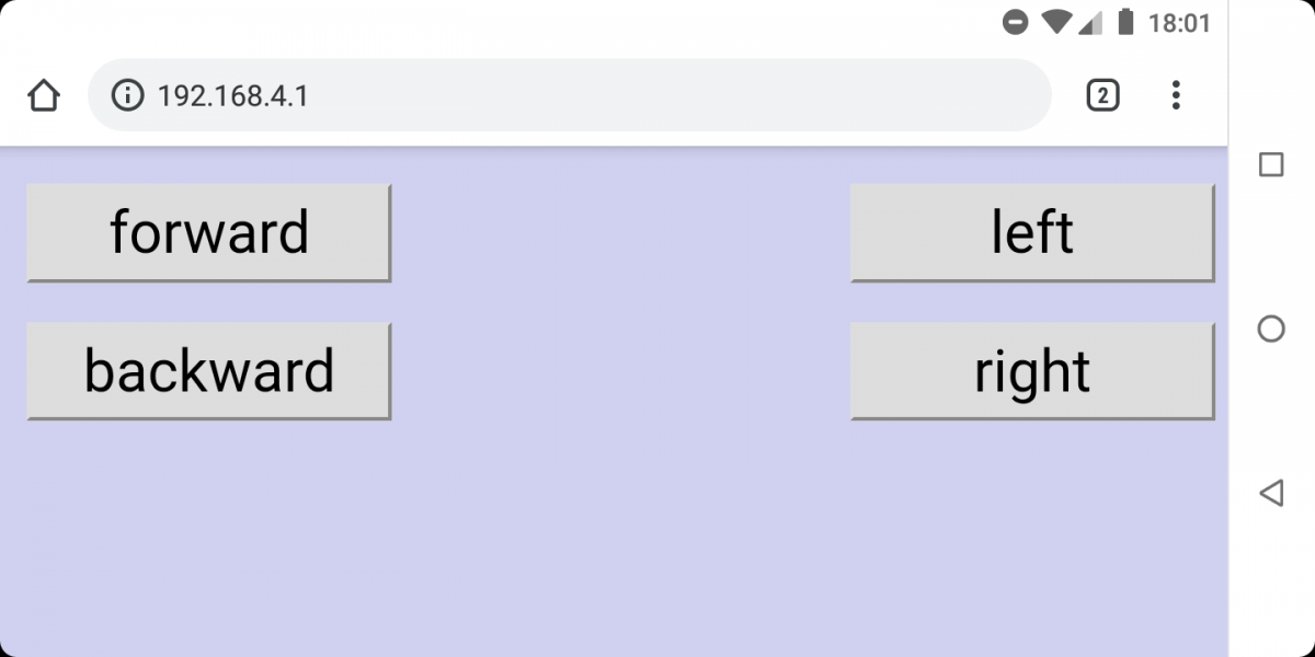
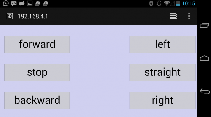
If your rc model would offer an access point and run a webserver, then you could control your model with a webbrowser running on your smartphone – no matter whether this is a Windows or Android device or an iPhone.

The PiKoder/SSC wRX (see below) is well suited as a hardware platform for this concept: the ESP8266-01 offers the access point and runs the webserver, the PiKoder/SSC manages all realtime aspects of controlling the servos and the electronic speed control.

pikoder_ssc_wrx-catalogue-image-png

PiKoder/SSC wRX

The standard configuration of the PiKoder/SSC wRX requires the ESP8266-01 to act as a transparent bridge. Since we will be needing a webserver, we would have to flash this wifi controller with a new firmware. This can be easily accomplished by using the latest Arduino IDE which is supporting generic ESP8266 modules.

The new controller firmware is open source and would be available through the github repository makerprojects/httpRC. After downloading open the sketch in the Arduino IDE. At the beginning of the source code you will find the settings recommended for compiling the program. [Update December 27, 2018: The httpRC sketch has been completely revised and updated. Please check this blog for more details.]

In order to flash the ESP8266-01 you will need an USB-Serial converter, since the wifi module does not feature a USB port. Please keep in mind also, that the ESP8266 requires a supply voltage of 3,3 Volts – the board is not 5 V tolerant! The offering of USB-Serial converter offering a 3,3 Volt supply as well as 3,3 Volt signal level is limited; therefore it might be easier to use a converter with 5 V supply and 3,3 V signal level such as the PL2303TA readily available at ebay (shown below) and build your own converter from 5 V to 3,3 V.

usb-connector-ebay

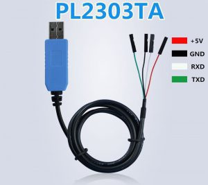
USB-Serial connector

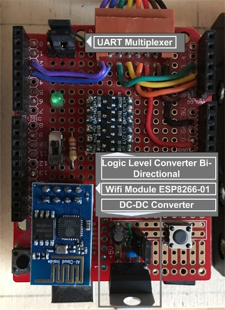
Since you would need a “reset” and “program” button for flashing the module you might consider to construct the little adapter shown below using a prototype board.

programmieradapter-esp8266

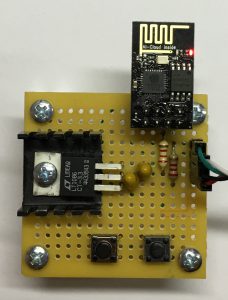
Programming adapter for the ESP8266-01

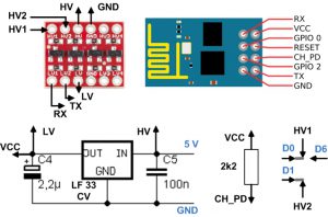
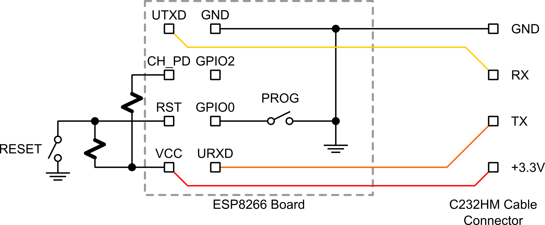
The schematic for the programming is shown below.

esp8266_flash_prog_board_sch

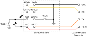
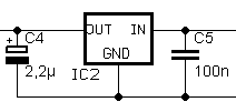
The conversion of the 5 V provided by the USB-Serial adapter to 3,3 V follows the design of the PiKoder/SSC wRX and requires a standard low drop voltage controller LF 33 CV ( please refer to the following excerpt of the PiKoder/SSC wRX schematic; the 5 V input would be to the left, the output is to the right).

spannungsanpassung

Unfortunately the flashing of the ESP8266 does not start automatically as you might be used to when downloading a program into your Arduino but has to be initiated manually. You would push the RST and PROG button simultaneously and release the RST button while still holding the PROG button. After releasing the PROG button, the module would be in flash mode. Now you would start uploading the program. Now you would start uploading the program. Once the upload is complete your controller would require another reset prior to being operational. Once the upload is complete your controller would require another reset prior to being operational.