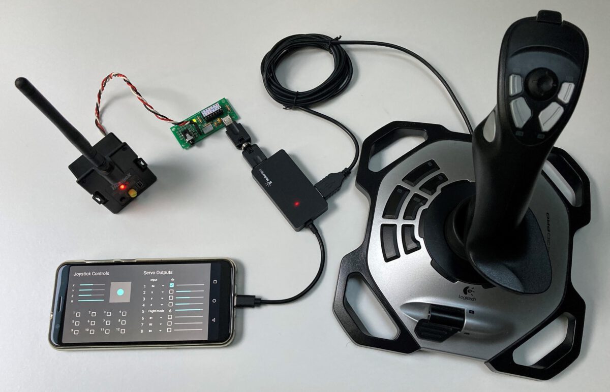
The previous blog described how the originally used remote control transmitter can be replaced by an iRangeX multi-protocol module and how the entire setup can be simplified.
In this blog, an even more compact structure is described in which the USB hub, the USB2PPM PiKoder and the multi-protocol module are mechanically combined into one unit, which then only needs to be connected to the smart device and the joystick.
The following steps are required for the implementation:
-
- Extend the USB hub cable
- Modify USB2PPM PiKoder with USB connector
- Realize mechanical rack
- Assemble and wire modules
Extend the USB hub cable
The common USB OTG hubs (on the go) usually have a very short connection cable (0.1 – 0.15 m). In practical use, this results in restrictions, since the hub must always be close to the smart device and possibly hangs in the air next to the holder and so a “rigid connection” with the PiKoder is not possible.
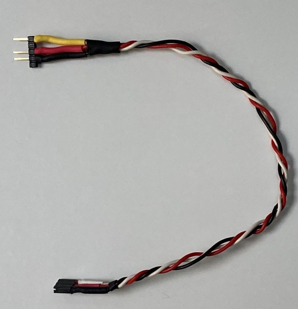
The extension of the connection cable is not a problem. It is only to be noted that an OTG connector with the corresponding coding (see picture) is still used as the connector, because otherwise the hub will not be recognized and will not be supplied with voltage.
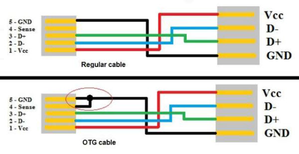
The easiest way to extend the extension is to solder a piece of USB cable of the desired length to the hub board and attach the existing plug with the short cable end to the other end and fix it with shrink tubing.
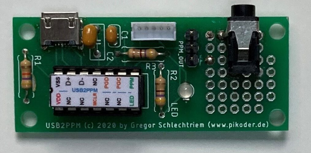
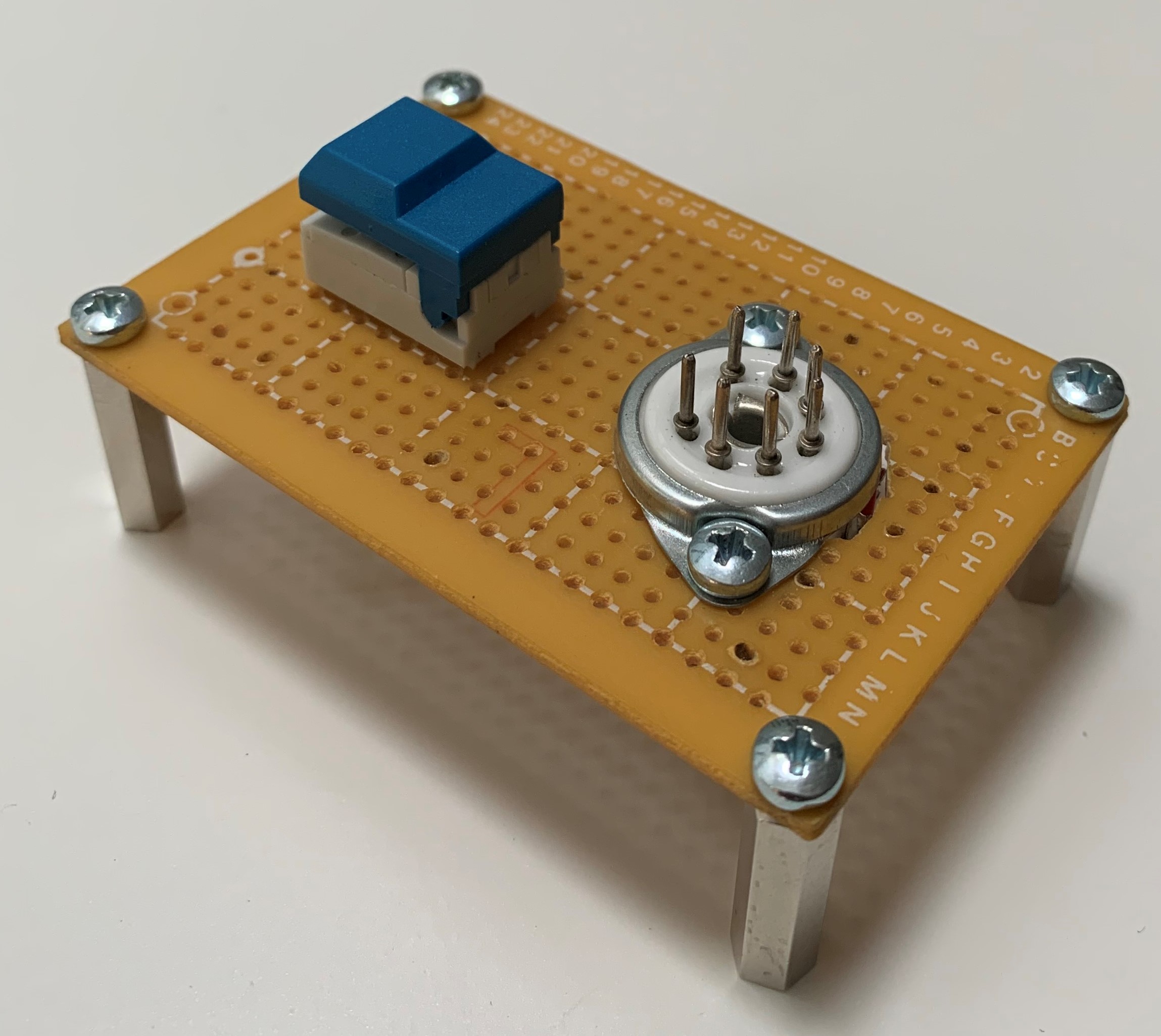
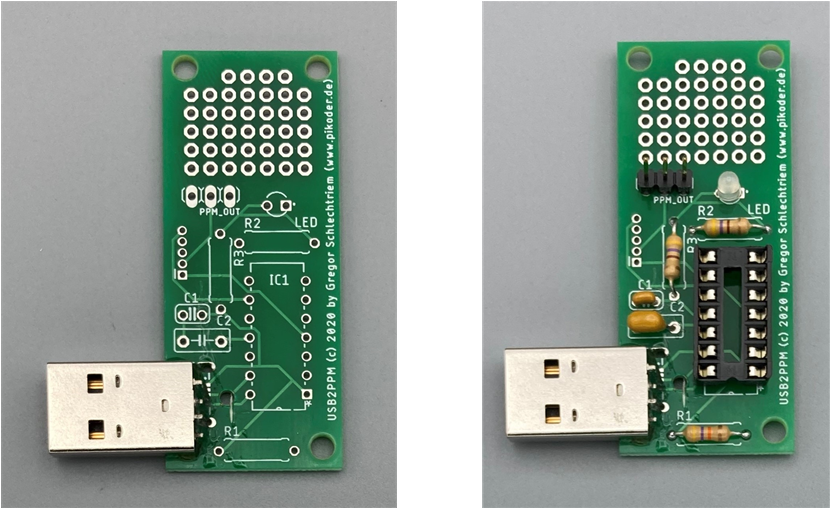
Modify USB2PPM PiKoder with USB connector
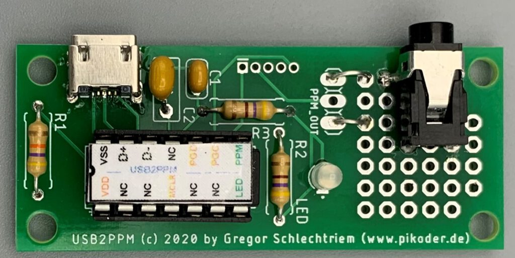
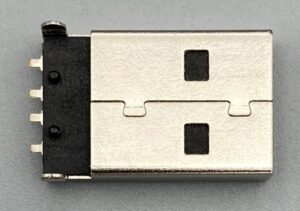 For the direct connection between the USB hub and the PiKoder, the USB2PPM requires a USB plug (see picture on the right) instead of the normal USB micro socket. So that the connector can be installed, saw the circuit board in order to then be able to push through the fastening straps. In addition, a hole is required in order to be able to wire the connection cables of the plug (see picture below).
 Then stick the connector to the circuit board with two-component adhesive and equip the circuit board with the remaining components (see pictures below). Note: In the further course of the project I replaced the three-pin header with a Molex connector.
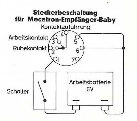
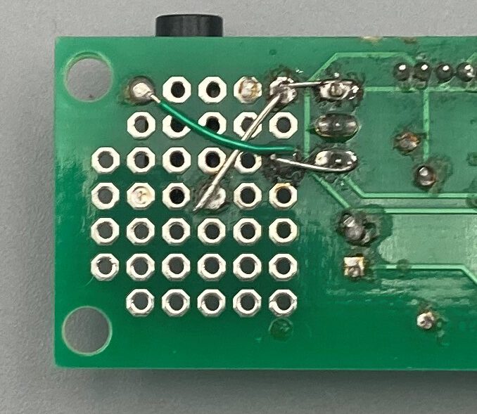
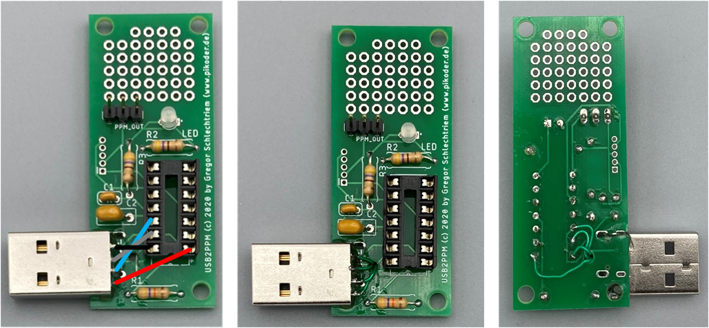
Finally connect the pins of the USB connector with the corresponding PiKoder pins; a thin, insulated wire is used for this. The following pictures show the schematic connection and then you can see the actual wiring on the underside of the circuit board.
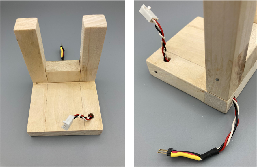
Realize mechanical rack
The subrack consists of a simple angled wooden structure. The square base plate with a side length of 85 mm accommodates the hub and the USB2PPM Pikoder. The multi-protocol module is clamped in the vertical fork. To improve the appearance of the cable routing, I drilled a corresponding channel.
Assemble and wire modules
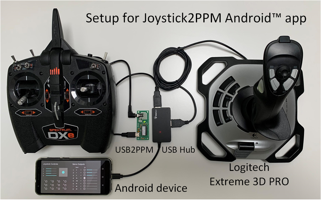
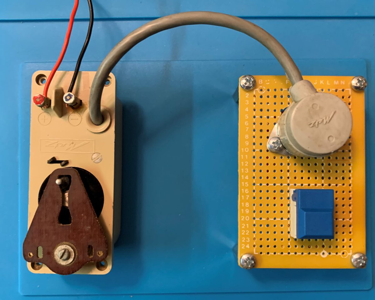
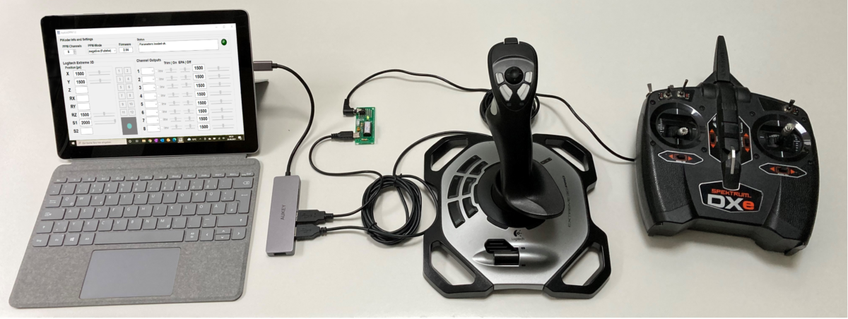
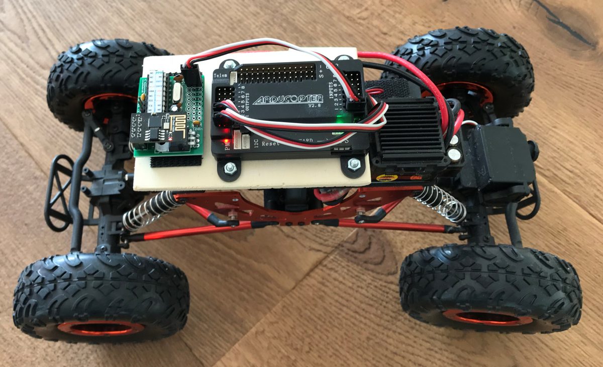
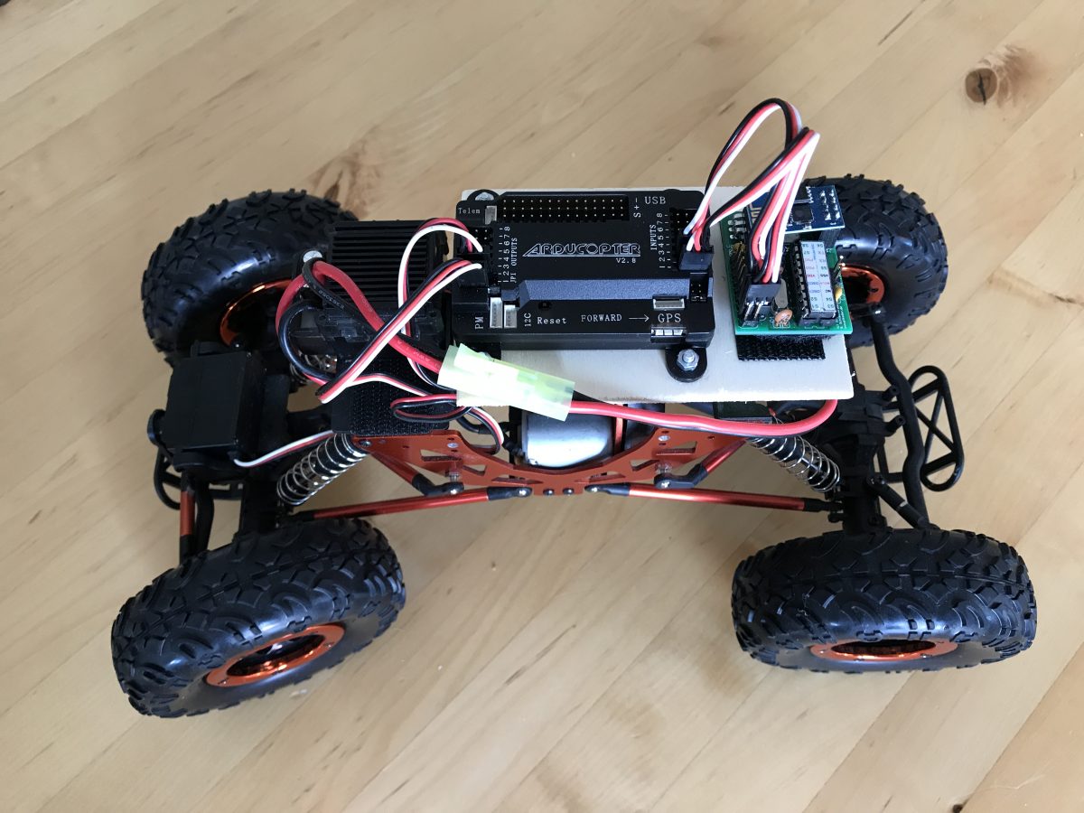
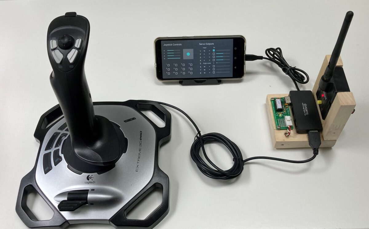
You can see the complete setup in the following pictures. The hub is fixed with double-sided adhesive tape, the USB2PPM PiKoder is plugged in and fixed with screws through the two front mounting holes. It is best to use some washers as spacers so that the circuit board does not bend.
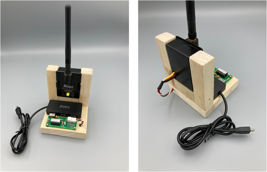
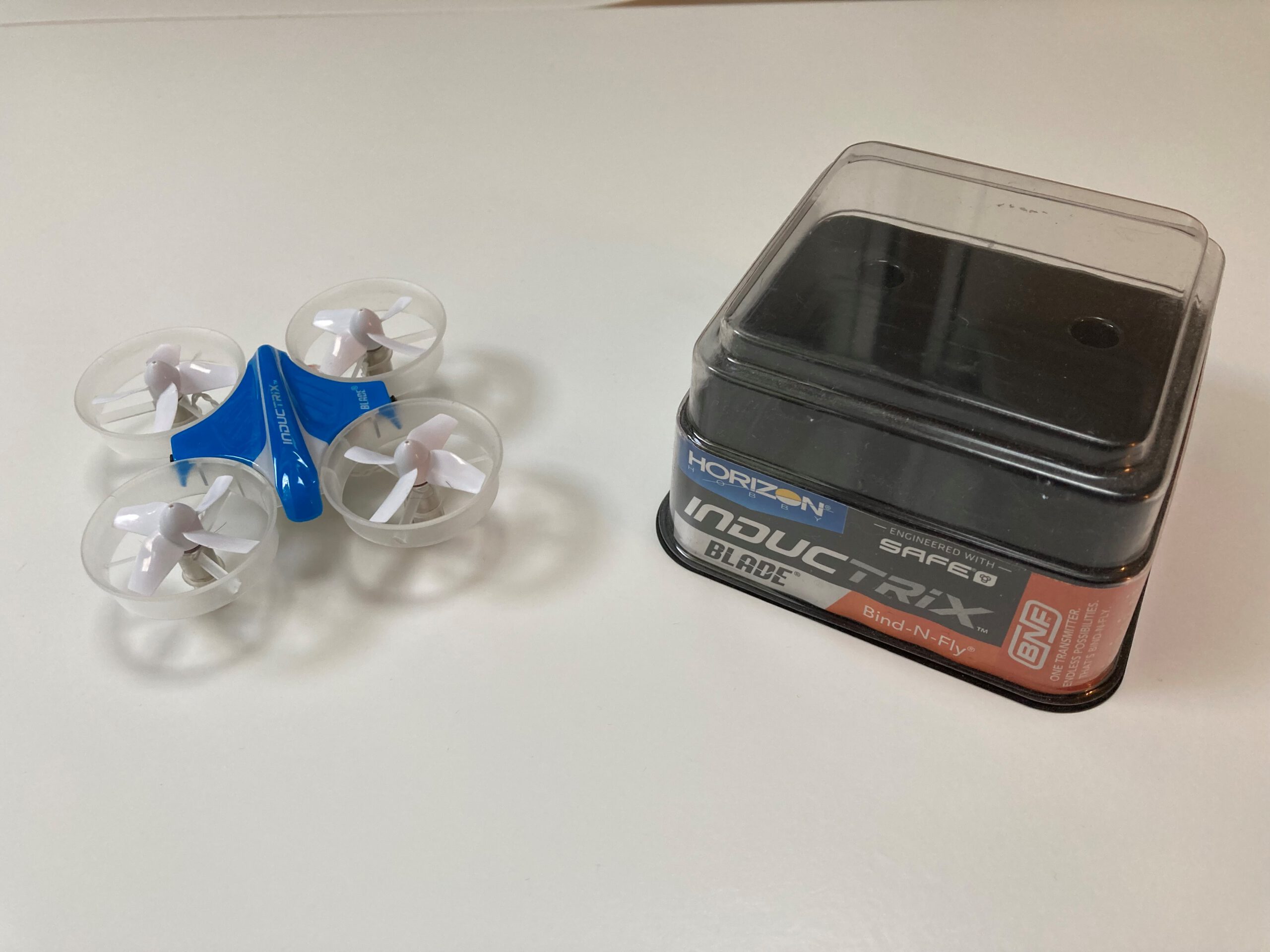
With the micro USB connector, the “compact transmitter” is initially intended for connection to an Android device. With a small adapter, e.g. from Micro USB to USB C plug, the transmitter can of course be easily connected to a Surface Notebook.