The sketch ArduinoDTX implements a feature rich RC addressing all needs of a state-of-the-art transmitter on an Arduino. It is based on fully digital encoding of all control information in the miniSSC – protocol rather than using a PPM frame. This fully digital encoding enables transmitting over a transparent serial channel such as Bluetooth, Wifi, and XBee. As a receiver for e.g. Bluetooth a PiKoder/SSC RX would be deployed.
This digital RC transmitter is based on the Open Source project arduinorc by Richard Goutorbe and thus inheriting the respective full feature set such as:
- up to 9 proportional channels (Nano), 6 channels by default (Uno)
- up to 6 additional digital channels (switches)
- 9 model memories
- Dual rate/Exponential switch
- Throttle cut switch
- 2 programmable mixers
- End point adjustment, Potentiometer and Servo calibration
- Throttle security check at startup
- Optional Transmitter battery low voltage alarm
- Programmable with Linux or Windows via USB (terminal application)
The original arduinorc-sketch has been modified and became the ArduinoDTx sketch, which outputs all channel information in the miniSSC-format rather than a PPM-pulse frame on Arduino pin D6. Every time a stick position would change a miniSSC message is generated. The PPM output has been removed completely.
The ArduinoDTx sketch is open source and provided through a respective github repository under the terms of the GNU General Public License Version 3.
Prototype setup: Digital four channel RC
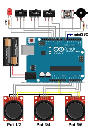
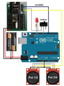
Schematic setup of the Arduino Digtial RC transmitter
An RC transmitter with four channels will serve as a prototype project. As shown in the image two Thumb-Joysticks are evaluated by the Arduino (Pot 1/2 and Pot 3/4 in the above schematic). The connection to the Arduino’s analog pins is through a proto-shield. This shield does also accomodate the mode switch and the LED with the respective 270R resistor.
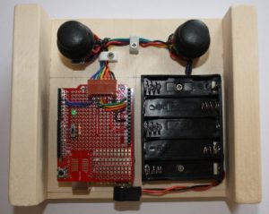
The RC is designed for battery operation. To guarantee the required minimum voltage of 6 V for the Arduino – even when using rechargeable batteries with a nominal voltage of 1,2 V – a battery holder for five AA elements has been selected. The two side panels support your palm operating the remote control and would enhance the user comfort significantly.
Please note that the USB port of the Arduino is easily accessible. This allows you to download software upgrades but also to customize the RC to your application.
Commissioning and testing
Test setup Arduino Digtial RC transmitter
For commissioning the RC you would download the arduinodtx sketch (.ino-file) which is provided through an respective github repository. Please note that building the sketch requires the Arduino “TimerOne”-library.
After you have uploaded the sketch to your Arduino the easiest way to test the RC would be to build the “wired remote control” shown to the right using a PiKoder/SSC evalutation board. In the standard configuration the pots 1-4 would control the respective servo channels 1-4 of the PiKoder/SSC.
If you wanted to customize your RC transmitter then you would hve to follow the steps described on the arduinorc-page. All commandos for programming the arduinorc are still available to you – for more information please refer to the (arduinorc command documentation).
Using Bluetooth communication
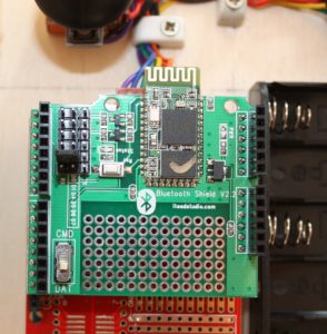
Bluetooth shield configuration for Arduino Digtial RC transmitter
You can easily customize the digital remote control to a Bluetooth RC with an ITEAD-Bluetooth Shield and then use the PiKoder/SSC RX as a readily available and fully compatible 8 channel receiver. Since the transmission is based on a tranparent serial protocol there are no changes needed in the sketch and the complete feature set is also available for the Bluetooth RC.
The transmitter setup is shown in the image. Prior to operating the RC the connection between the wifi modules has to be configured. Please refer to the PiKoder/SSC RX User Manual for a detailed description.
Using WLAN communication
You can also easily customize the digital remote control to a Wifi RC by adding a logic level converter, a dc-dc converter, two jumpers as UART multiplexers (to allow for programming the wifi radio) and an ESP8266-01 Wifi module and then use the PiKoder/SSC wRX as a readily available and fully compatible 8 channel receiver. The hardware setup and the programming of the wifi radios is described in great detail in the blog Arduino WLAN RC Transmitter.
Additional Application Examples
In order to increase the range of your radio control you can upgrade from Bluetooth to XBee. The setup is described in the blog Arduino based XBee radio control and in the PiKoder/SSC Application Note #3: XBee Communication.
